Programmable logic, Logic timer configuration – Basler Electric DECS-400 User Manual
Page 181
9369700990 Rev R
169
Programmable Logic
The DECS-400 utilizes programmable logic functionality in the form of multiplexors, AND gates, OR
gates, NOT gates, and timers. Refer to Table 23. Inputs to the logic are in the form of discrete information
including switching inputs, system status data, protection status data, limiter status data, alarm status
data, and PSS status data. The outputs of the programmable logic module can be used to control the
relay outputs as well as various other functions inside the DECS-400 such as control functions (start/stop,
mode select, etc.), protection functions (field overvoltage enable, field overcurrent enable, etc.), limiter
functions (OEL enable, UEL enable, etc.), and PSS functions.
The programmable logic capabilities of the DECS-400 are accessed through the Logic screen of
BESTCOMS. Predefined logic schemes, saved as files, can be accessed and activated through
BESTCOMS. If desired, a predefined logic scheme can be altered to accommodate the specific needs of
an application.
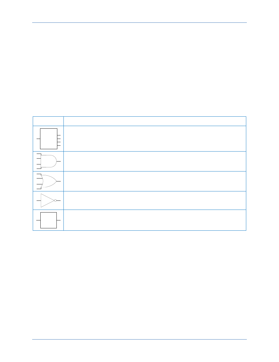
Table 23. Programmable Logic Functionality
Symbol
Description
Multiplexor - The input line is connected to all output lines.
AND Gate - Produces an output of 1 when all inputs are 1, otherwise the output is 0.
OR Gate - If any or all of the inputs are 1, the resulting output value is a 1. The output is
0 only when all inputs are 0.
NOT Gate - Changes the input to its opposite.
Timer - Places a time delay between two points in the logic.
Logic Timer Configuration
The logic timer element has four available logic modes: pickup/dropout, one-shot retriggerable, one-shot
non-retriggerable, and oscillator. The four timer modes are illustrated in Figure 105.
For each timer mode, a logic 1 at the Block Inhibit input inhibits timer operation.
Timer delay settings (T1 and T2) are expressed in milliseconds. T1 is the logic 1 time delay while T2 is
the logic 0 time delay.
The one-shot retriggerable and non-retriggerable timers are initiated by a positive edge trigger at the timer
input.
The input of the oscillator timer is always ignored and has no effect on oscillator timer operation.
MUX
X1
U1
U4
U3
U2
TIMER
DECS-400
Programmable Logic