Decs-400 functional description – Basler Electric DECS-400 User Manual
Page 69
9369700990 Rev R
57
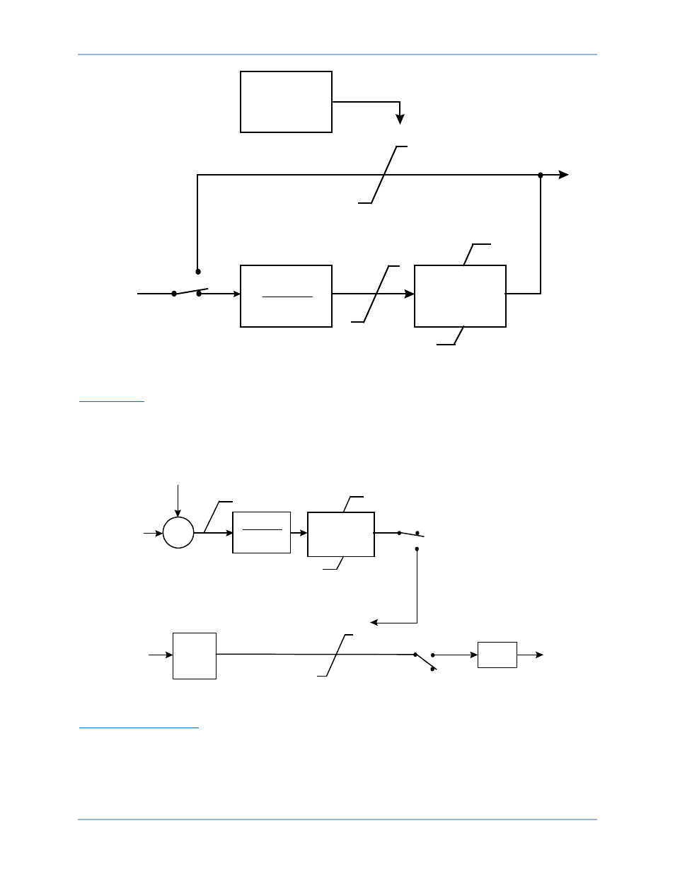
Figure 25. Washout Filter and Logic Limiter
Output Stage
Prior to connecting the stabilizer output signal to the voltage regulator input, adjustable gain and limiting
are applied. The stabilizer output is connected to the voltage regulator input when the software switch
SSW 10 setting is On. SSW 10 is accessed on the Control tab of the BESTCOMS PSS screen.
Processing of the stabilizer output signal is illustrated in Figure 26.
Figure 26. Output Stage
Terminal Voltage Limiter
Since the PSS operates by modulating the excitation, it may counteract the voltage regulator’s attempts to
maintain terminal voltage within a tolerance band. To avoid creating an overvoltage condition, the PSS
has a terminal voltage limiter (shown in Figure 26) that reduces the upper output limit to zero when the
generator voltage exceeds the terminal voltage setpoint. The limit setpoint is normally selected such that
the limiter will eliminate any contribution from the PSS before the timed overvoltage or volts per hertz
protection operates.
SSW 9
Logic Limiter
V
lmt_lo
V
lmt_hi
s T
w5
1 + s T
w5
V
PSS_ULMT
V
PSS_LLMT
V
PSS_ULMT
V
PSS_LLMT
Phase Lead
Block
V
ST
Terminal
Voltage Limiter
P0026-22
12-13-04
Disable
Enable
Σ
+
Generator
Terminal Voltage
-
Terminal Voltage
Set-Point
1
1 + s T
L4
SSW 8
PSS Output
Before Gains
and Limits
K
s
VPSS_ULMT
Ramp
Limiter
0
0
V
PSS_SLMT
P0026-23
12-14-04
Disable
SSW 10
PSS Output
Scale
Enable
On
Off
VPSS_LLMT
DECS-400
Functional Description