Basler Electric DECS-400 User Manual
Page 66
54
9369700990 Rev R
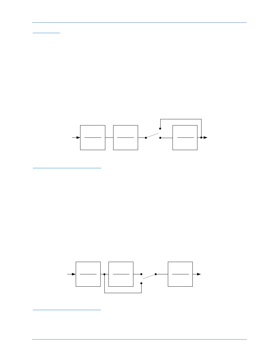
Speed Signal
The speed signal is converted to a constant level that is proportional to the shaft speed (frequency).
Two high-pass (frequency washout) filter stages are applied to the resulting signal to remove the average
speed level and produce a speed deviation signal. This ensures that the stabilizer reacts only to changes
in speed and does not permanently alter the generator terminal voltage reference.
The frequency washout filter stages are controlled by time constant settings Tw1 and Tw2. Each time
constant setting has a setting range of 1 to 20 seconds with 0.01 second increments. Tw1 and Tw2 are
accessed on the Parameters tab of the BESTCOMS PSS screen.
Low-pass filtering of the speed deviation signal can be enabled or disabled through software switch
SSW 0. SSW 0 is accessed on the Control tab of the BESTCOMS PSS screen. The low-pass filter time
constant is adjusted by the TI1 setting which has a setting range of 0 to 0.2 seconds with 0.01 second
increments. TI1 is accessed on the Parameters tab of the BESTCOMS PSS screen.
Figure 19 shows the high-pass and low-pass filter transfer function blocks in frequency domain form. (The
letter s is used to represent the complex frequency or Laplace operator.)
Figure 19. Speed Signal
Generator Electrical Power Signal
Figure 20 illustrates the operations performed on the power input signal to produce the integral of
electrical power deviation signal.
The generator electrical power output is derived from the generator VT secondary voltages and generator
CT secondary currents applied to the DECS-400.
The power output is high-pass (washout) filtered to produce the required power deviation signal. if
additional washout filtering is desired, a second high-pass filter can be enabled by software switch
SSW 1. The first high-pass filter is controlled by time constant setting Tw3 and the second high-pass filter
is controlled by time constant setting Tw4. Each time constant has a setting range of 1 to 20 seconds with
0.01 second increments. Tw3 and Tw4 are accessed on the Parameters tab of the BESTCOMS PSS
screen. Software switch SSW 1 is accessed on the Control tab of the BESTCOMS PSS screen.
After high-pass filtering, the electrical power signal is integrated and scaled, combining the generator
inertia constant (2H) with the speed signal. Low-pass filtering within the integrator is controlled by time
constant TI2. TI2 has a setting range of 1 to 20 seconds with 0.01 second increments. The primary PSS
unit inertia, "H", has a setting range of 1 to 25 MW-s/MVA with 0.01 Mw-s/MVA increments. TI2 and "H"
are accessed on the Parameters tab of the BESTCOMS PSS screen.
Figure 20. Generator Electrical Power Signal
Derived Mechanical Power Signal
The speed deviation signal and integral of electrical power deviation signal are combined to produce a
derived, integral of mechanical power signal.
An adjustable gain stage, Kpe, is provided and has a setting range of 0 to 2.00 with increments of 0.01.
Kpe is accessed on the Parameters tab of the BESTCOMS PSS screen.
SSW 0
Enable
Disable
Washed Out
Speed
Compensated
Frequency
P0026-13
11-19-04
sT
w1
1+ sT
w1
sT
w2
1+ sT
w2
1
1+ sT
l1
SSW 1
Disable
Enable
Power
Washed Out
Power
P0026-14
11-19-04
sT
w3
1+ sT
w3
sT
w4
1+ sT
w4
T
l2
/ 2H
1+ sT
l2
Functional Description
DECS-400