Basler Electric DECS-400 User Manual
Page 77
9369700990 Rev R
65
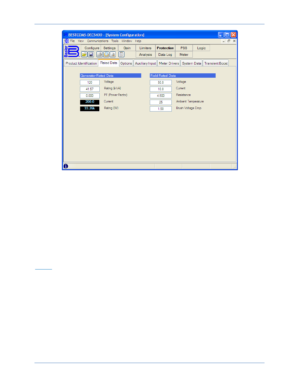
Figure 34. System Configuration Screen, Rated Data Tab
Field Rated Data – Current. The rated main field or exciter field current is entered in this setting field. (The
field type is selected on the Options tab of the System Configuration screen.) A setting of 0.1 to 9,999
Adc may be entered in 0.1 Adc increments.
Field Rated Data – Resistance. The level of field resistance at the nominal ambient temperature is
entered in this setting field. A value of 0 to 99.999 ohms may be entered in 0.001 ohm increments. This
setting field is enabled only for main field applications.
Field Rated Data – Ambient Temperature. The ambient field temperature is entered in this setting field
and is used to calculate the generator main field temperature. A value of 0 to 572
°C may be entered in
1
°C increments. This setting field is enabled only for main field applications.
Field Rated Data – Brush Voltage Drop. The brush voltage drop, at the field ambient temperature, is
entered in this setting field. A value of 0 to 20.00 V may be entered in 0.01 V increments. This setting field
is enabled only for main field applications.
Options
Options tab functions are shown in Figure 35 and described in the following paragraphs.
Voltage Sensing. This setting selects the generator voltage sensing configuration used and the phase
rotation for three-phase sensing configurations. Three voltage sensing options may be selected from the
drop-down menu. AC 1-Phase selects single-phase voltage sensing, connected across generator phases
A and C. ABC 3-Phase selects three-phase voltage sensing and ABC phase rotation. ACB 3-Phase
selects three-phase voltage sensing and ACB phase rotation.
Field Type. This setting selects excitation control for either the generator main field or the exciter field.
The mode selected determines the corresponding rated data and PID parameters for either main field or
exciter field control. Either Main Field or Exciter Field may be selected from the drop-down menu.
Bridge Control Signal. This setting selects the control signal type and range supplied by the DECS-400.
The control signal type and range is selected from the drop-down menu. 0-> +10V selects a control signal
with a range of 0 to 10 Vdc. –10V-> +10V selects a control signal with a range of –10 Vdc to +10 Vdc.
4-> 20mA selects a control signal with a range of 4 to 20 mAdc.
DECS-400
BESTCOMS™ Software