Basler Electric DECS-400 User Manual
Page 128
116
9369700990 Rev R
Test Signal
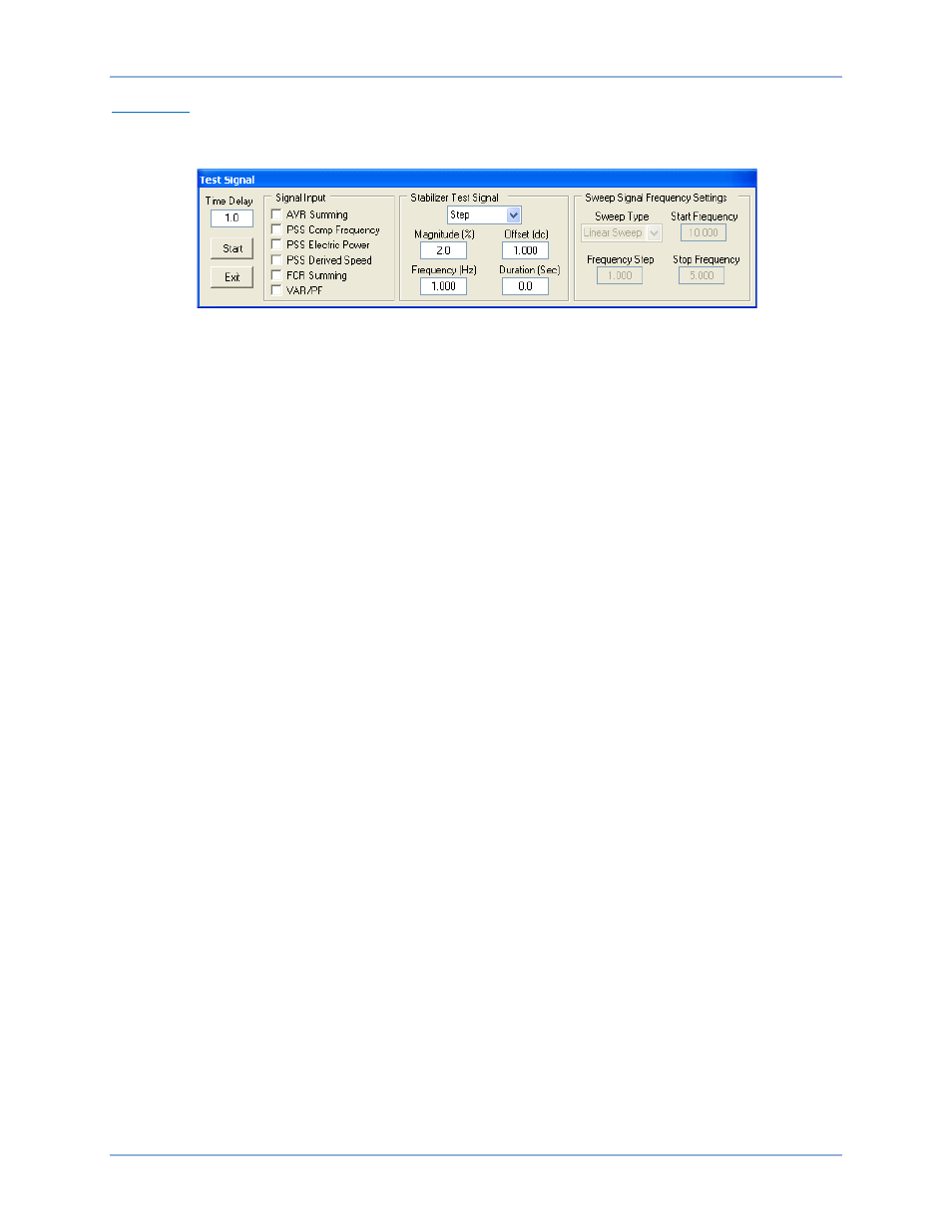
Clicking the Time Response button on the Analysis screen displays the Test Signal screen shown in
Figure 81. This screen’s settings and controls are described in the following paragraphs.
Figure 81. Test Signal Screen
Time Delay. This setting selects the length of time between when the Start button is clicked and testing
begins. A setting of 0 to 125 seconds may be entered in 0.1 second increments.
Start Button. When clicked, this button initiates testing (after the Time Delay setting expires).
Exit Button. Clicking this button returns to the Analysis screen.
Signal Input. This setting selects the point in the PSS circuitry where the test signal is applied. Test points
include AVR Summing, PSS Comp Frequency, PSS Electric Power, PSS Derived Speed, FCR Summing
and Var/PF.
Stabilizer Test Signal – Type. This setting is used to disable the internal PSS test signal or select any one
of four test signal types: Step, Sine, Swept Sine, or External.
Stabilizer Test Signal – Magnitude (%). This setting adjusts the magnitude (excludes gain for external
signal) of the stabilizer test signal. When the test signal type is None, this setting is disabled (grayed out).
The magnitude has a setting range of –10 to +10% with 0.1% increments.
Stabilizer Test Signal – Offset (dc). This setting adjusts the dc offset of the stabilizer test signal. When the
test signal type is None or Step, this setting is disabled (grayed out). The offset can be adjusted over the
range of –10 to +10 in 0.001 increments.
Stabilizer Test Signal – Frequency (Hz). This setting adjusts the frequency of the stabilizer test signal.
When the test signal type is None, Swept Sine, or External, this setting is disabled (grayed out). The
frequency can be adjusted over a range of 0 to 20 Hz in 0.001 Hz increments.
Stabilizer Test Signal – Duration (Sec). This setting adjusts the duration of the test signal. For sine and
external test signals, this is the total test duration. For step test signals, this is the “on” period of the step
signal. When the test signal type is None or Swept Sine, this setting is disabled (grayed out). The duration
can be adjusted over a range of 0 to 49,999 seconds in 0.1 second increments.
Sweep Signal Frequency Settings – Sweep Type. This setting is enabled only when the test signal type is
Swept Sine. A linear sweep type is selected by entering a 0. A logarithmic sweep type is selected by
entering a 1.
Sweep Signal Frequency Settings – Start Frequency. This setting is enabled only when the test signal
type is Swept Sine. The starting frequency for the swept sine test signal is selected with this setting. The
Start Frequency has a setting range of 0 to 20 Hz with 0.001 Hz increments.
Sweep Signal Frequency – Frequency Step. This setting is enabled only when the test signal type is
Swept Sine. The frequency step for the swept sine test signal is selected with this setting. For linear
sweeps, the test signal frequency is incremented by “step” every half-cycle of the system frequency. For
logarithmic sweeps, the test signal frequency is multiplied by 1.0 + step every half-cycle of the system
frequency. The frequency step has a setting range of 0 to 1 with 0.001 increments.
Sweep Signal Frequency – Stop Frequency. This setting is enabled only when the test signal setting is
Swept Sine. The end frequency for the swept sine test signal is selected with this setting. The stop
frequency has a setting range of 0 to 20 Hz with 0.001 Hz increments.
BESTCOMS™ Software
DECS-400