Basler Electric DECS-400 User Manual
Page 129
9369700990 Rev R
117
RTM Step Response
Clicking the Step Response button on the Analysis screen displays the Real-Time Metering Step
Response screen. This screen has four metering fields, an alarms window, an Exit button, a checkbox to
trigger data logging on a step change, and four tabs.
The metering fields display the average generator output voltage, the level of field current, the reactive
power level, and the power factor.
The alarms window displays any active alarms triggered by a step change.
Clicking the Exit button closes the RTM Step Response screen and returns to the Analysis screen.
Selecting the “Trigger Data Logging on Step Change” checkbox causes the DECS-400 to log a data
record when a setpoint step change is performed.
Four RTM Step Response screen tabs, labeled AVR, FCR, VAR, and PF are described in the following
paragraphs.
AVR Tab
AVR tab functions are shown in Figure 82 and described in the following paragraphs.
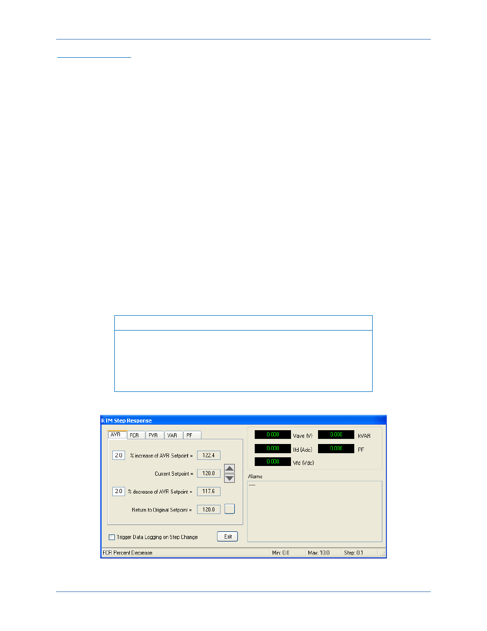
The AVR tab of the RTM Step Response screen enables step changes to be applied to the AVR setpoint.
Step changes that increase or decrease the AVR setpoint can be applied by clicking the increment (up
arrow) or decrement (down arrow) button. Step-change setting fields (one for increase and one for
decrease) establish the percent change in the AVR setpoint that occurs when the increment or decrement
button is clicked. A setting of 0 to 10% may be entered in 0.1% increments. A read-only setpoint field
indicates the current setpoint and what the setpoint will be when a step change occurs. A button is
provided to return the AVR setpoint to its original value before any step changes were invoked. This
original value is the AVR setpoint entered on the AVR/FCR/FVR tab of the BESTCOMS Settings screen
and is displayed in the read-only field adjacent to the button.
Notes
If logging is in progress, another log cannot be triggered.
Response characteristics displayed on the RTM Step Response
screen are not automatically updated when the DECS-400 operating
mode is switched externally. The RTM Step Response screen must be
manually updated by exiting and then reopening the screen.
A checkbox enables the triggering of a data log when a step change is initiated.
Figure 82. RTM Step Response Screen, AVR Tab
DECS-400
BESTCOMS™ Software