Communication connections – Basler Electric DECS-400 User Manual
Page 148
136
9369700990 Rev R
Communication Connections
DECS-400 communication ports consist of a front-panel RS-232 port (Com 0), a rear-panel RS-485 port
for DECS-400-to-DECS-400 communication (Com 1), a rear-panel RS-485 port for Modbus
communication (Com 2), and an RJ-11 modem jack (J1). DECS-400 communication ports are described
in the following paragraphs.
Com 0
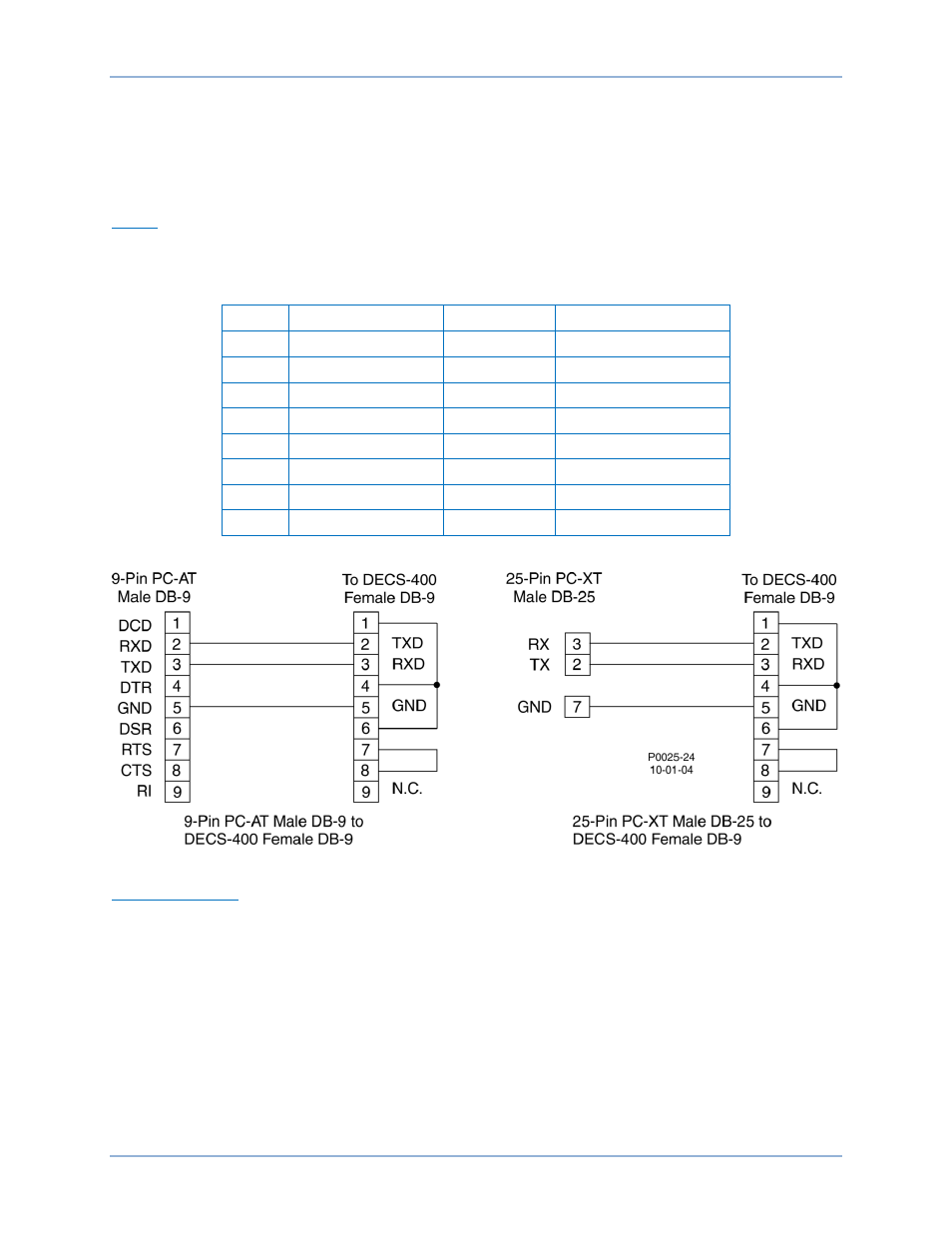
Table 19 identifies the pin functions of this front-panel, female DB-9 connector. Figure 96 illustrates the
connections between Com 0 and a PC.
Table 19. Com 0 Pin Functions
Pin
Function
Name
Direction
1
Shield
—
N/A
2
Transmit Data
TXD
From DECS-400
3
Receive Data
RXD
Into DECS-400
4
No Connection
—
N/A
5
Signal Ground
GND
N/A
6
No Connection
—
N/A
7
No Connection
—
N/A
8
No Connection
—
N/A
Figure 96. Com 0 to PC Connections
Com 1 and Com 2
Com 1 and Com 2 consist of rear-panel RS-485 ports. Com 1 is an ASCII port used for communication
with another DECS-400 when operating in a redundant system configuration. Shielded, twisted-conductor
cable is recommended for Com 1 connections. Com 2 is intended for polled communication over a
Modbus network. Twisted-pair cable is recommended for Com 2 connections. Terminal functions for Com
1 and Com 2 are identified in Table 14. Figure 97 illustrates the Com 1 connections used for DECS-400-
to-DECS-400 communication.
Installation
DECS-400