Data log, Figure 70, Figure 70) – Basler Electric DECS-400 User Manual
Page 114
102
9369700990 Rev R
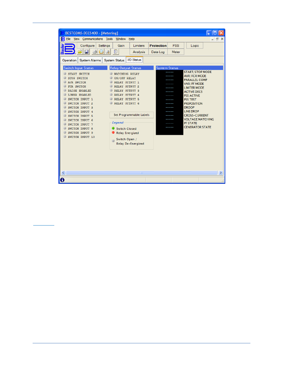
Figure 70. Metering Screen, I/O Status Tab
Data Log
The Data Log screen consists of five tabs: Log Setup, Logic Triggers, Mode Triggers, Level Triggers/Log
Selection, and Trending. Clock the Data Log button on the tool bar to view the Data Log screen.
Log Setup
Log Setup tab parameters and controls are shown in Figure 71 and described in the following paragraphs.
Data Log Setup – Data Logging Enabled. This setting enables and disables data logging.
Data Log Setup – Pre-Trigger Points. This setting selects the number of data points that are recorded
prior to a data log being triggered. A value of 0 to 599 may be entered in increments of 1.
Data Log Setup – Pre-Trigger Duration (sec). This read-only field displays the length of time that pre-
trigger data points are recorded. The value displayed is determined by the Pre-Trigger Points and Sample
Interval settings.
Data Log Setup – Post-Trigger Points. This read-only field displays the number of data points that are
recorded after a data log is triggered. The value displayed is determined by the Pre-Trigger Points and
Sample Interval settings.
Data Log Setup – Post-Trigger Duration (sec). This read-only field displays the length of time that post-
trigger data points are recorded. The value displayed is determined by the Pre-Trigger Points and Sample
Interval settings.
Data Log Setup – Sample Interval (ms). This setting establishes the sample rate of the data points. When
the Generator Frequency setting (Configure screen, Options tab) is 60 Hz, a sample interval of 4.166 to
10,415.000 milliseconds may be selected from the pull-down menu. When the Generator Frequency
setting is 50 Hz, a sample interval of 5 to 12,500 milliseconds may be selected.
BESTCOMS™ Software
DECS-400