Underexcitation limiter – Basler Electric DECS-400 User Manual
Page 58
46
9369700990 Rev R
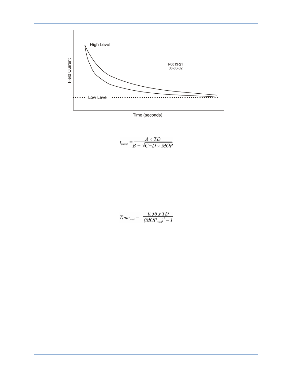
Figure 14. Inverse Time Characteristic for Takeover-Style OEL
The inverse time characteristic is defined by the following equation:
Where:
t
pickup
= time to pickup in seconds
A = –95.908
B = –17.165
C = 490.864
D = –191.816
TD = time dial setting <0.1, 20>
MOP = multiple of pickup <1.03, 2.5>
Once the field current decreases below the dropout level (95% of pickup), the function is reset based on
the following curve equation:
Each mode of operation (off-line and on-line) has a Low Level setting, a High Level setting, and a Time
Dial setting. Each Low Level setting has a setting range of 0 to 11,999 Adc with 0.01 Adc increments.
Each High Level setting has a setting range of 0 to 9,999 Adc with 0.01 Adc increments. Each Time Dial
setting has a setting range of 0.1 to 20 seconds with 0.1 second increments.
The two current thresholds are defined by the Off-Line Low Level, Off-Line High Level, On-Line Low
Level, and On-Line High Level settings. Each Low level setting has a setting range of 0 to 11,999 Adc
with 0.01 Adc increments. Each High Level setting has a setting range of 0 to 9,999 Adc with 0.01 Adc
increments. The Time Dial settings have a setting range of 0.1 to 20 seconds with 0.1 second increments.
Underexcitation Limiter
The underexcitation limiter UEL senses the leading var level of the generator and limits any further
decrease in excitation to prevent loss of synchronization and limit end-iron heating. The (UEL) operates in
all modes. Through user-configurable logic, the UEL can be disabled only in FCR mode. In this
circumstance, underexcitation is only annunciated—not limited.
An internally-generated UEL curve or user-defined UEL curve may be specified. If the customized curve
is selected and if a zero setting is entered for kW point 2 or kvar point 2, the UEL will use the internally-
generated UEL curve. The internally-generated curve is based on the desired reactive power limit level at
zero real power with respect to the generator voltage and current rating. The following equation illustrates
the internally-generated UEL curve:
Functional Description
DECS-400