Basler Electric DECS-400 User Manual
Page 200
188
9369700990 Rev R
2.
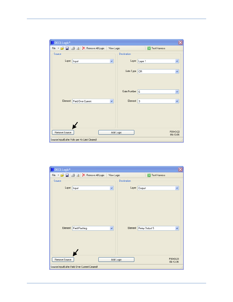
Figure 122 illustrates the DECS Logic window settings associated with this step. Disconnect the Field
Overcurrent Active input buffer from input 3 of OR gate 6 on logic layer 1. In Table 24, this
association is identified by “DESTINATION: Layer1 – InputBuffer.Field Over Current
Or6.Input3”.
Figure 122. Deletion of Layer1 InputBuffer.Field Over Current ---> Or6.Input3
3.
Figure A-18 illustrates the DECS Logic window settings associated with this step. Disconnect the
Buildup Active input buffer from the Output Relay #5 output buffer. In Table A-2, this association is
identified by “DESTINATION: OutputBuffer – InputBuffer.Field Flashing
Relay Output 5”.
Figure 123. Deletion of OutputBuffer - InputBuffer.Field Flashing ---> Relay Output 5
Programmable Logic
DECS-400