Basler Electric DECS-400 User Manual
Page 202
190
9369700990 Rev R
2.
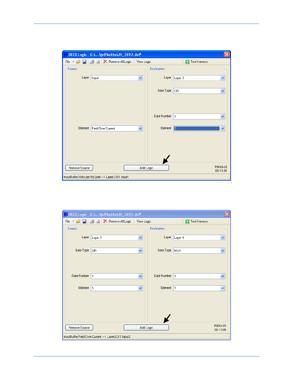
Figure 125 illustrates the DECS Logic window settings associated with this step. Connect the Field
Overcurrent Active input buffer to input 2 of OR gate 1 on logic layer 3. In Table 24, this association is
identified by “DESTINATION: Layer3 – InputBuffer.Field Over Current
Or1.Input2”.
Figure 125. Addition of Layer3 InputBuffer.Field Over Current ---> Layer3.Or1.Input2
3.
Figure 126 illustrates the DECS Logic window settings associated with this step. Connect the output
of OR gate 1 on layer 3 to the input of multiplexer 1 on layer 4. In Table 24, this association is
identified by “DESTINATION: Layer4 – Layer3.Or1.Output
Mux1.Input”.
Figure 126. Addition of Layer4 - Layer3.Or1.Output ---> Mux1.Input
Programmable Logic
DECS-400