Basler Electric DECS-400 User Manual
Page 79
9369700990 Rev R
67
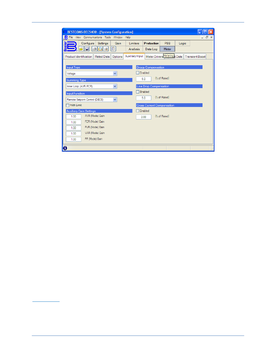
Figure 36. System Configuration Screen, Auxiliary Input Tab
Input Type. This setting selects either voltage (–10 Vdc to +10 Vdc) or current (4 to 20 mAdc) as the
control signal for the DECS-400 auxiliary input. Input type settings are selected from the drop-down
menu.
Summing Type. This setting selects the summing mode for the auxiliary input. When Inner Loop is
selected, the operating mode is either AVR or FCR. When Outer Loop is selected, the operating mode is
either var or power factor. Summing types are selected from the drop-down menu.
Input Function. This drop-down menu configures the auxiliary input to control the excitation setpoint, the
power system stabilizer (PSS), or limiter scaling. The auxiliary input is disabled by selecting “No Control”.
Regardless of the selection made, the auxiliary input can always be used for functions such as metering
and data logging.
Auxiliary Gain Settings. The five auxiliary gain setting fields, AVR, FCR, FVR, var, and PF, select the gain
which affects the setpoint of the selected operating mode. The signal applied to the auxiliary input is
multiplied by the auxiliary gain setting. Each gain setting has a range of –99.00 to +99.00 with an
increment of 0.01. A setting of zero disables the auxiliary input for that operating mode.
Droop Compensation. Enabling this setting allows the DECS-400 to provide droop compensation for
paralleled generators. Droop compensation is adjustable from –30% to +30% (in 0.1 percent increments)
of the generator rated terminal voltage.
Line Drop Compensation. Enabling this setting allows the DECS-400 to compensate for line drop between
paralleled generators. Line drop compensation is adjustable from 0 to 30.0% in 0.1 percent increments.
Cross Current Compensation. Enabling this setting allows the DECS-400 to provide reactive differential
gain for parallel generators. Cross current compensation is adjustable from –30.00 to +30.00 percent in
0.01 percent increments.
Meter Drivers
Meter Drivers tab functions are shown in Figure 37 and described in the following paragraphs.
Meter Driver 1 and Meter Driver 2. These settings enable and disable the meter driver outputs, select the
system parameters to be metered, and define the minimum and maximum values of the metered
parameters. The parameters to be metered are selected from the drop-down menus. The available
parameters are listed below:
DECS-400
BESTCOMS™ Software