Figure 97 – Basler Electric DECS-400 User Manual
Page 149
9369700990 Rev R
137
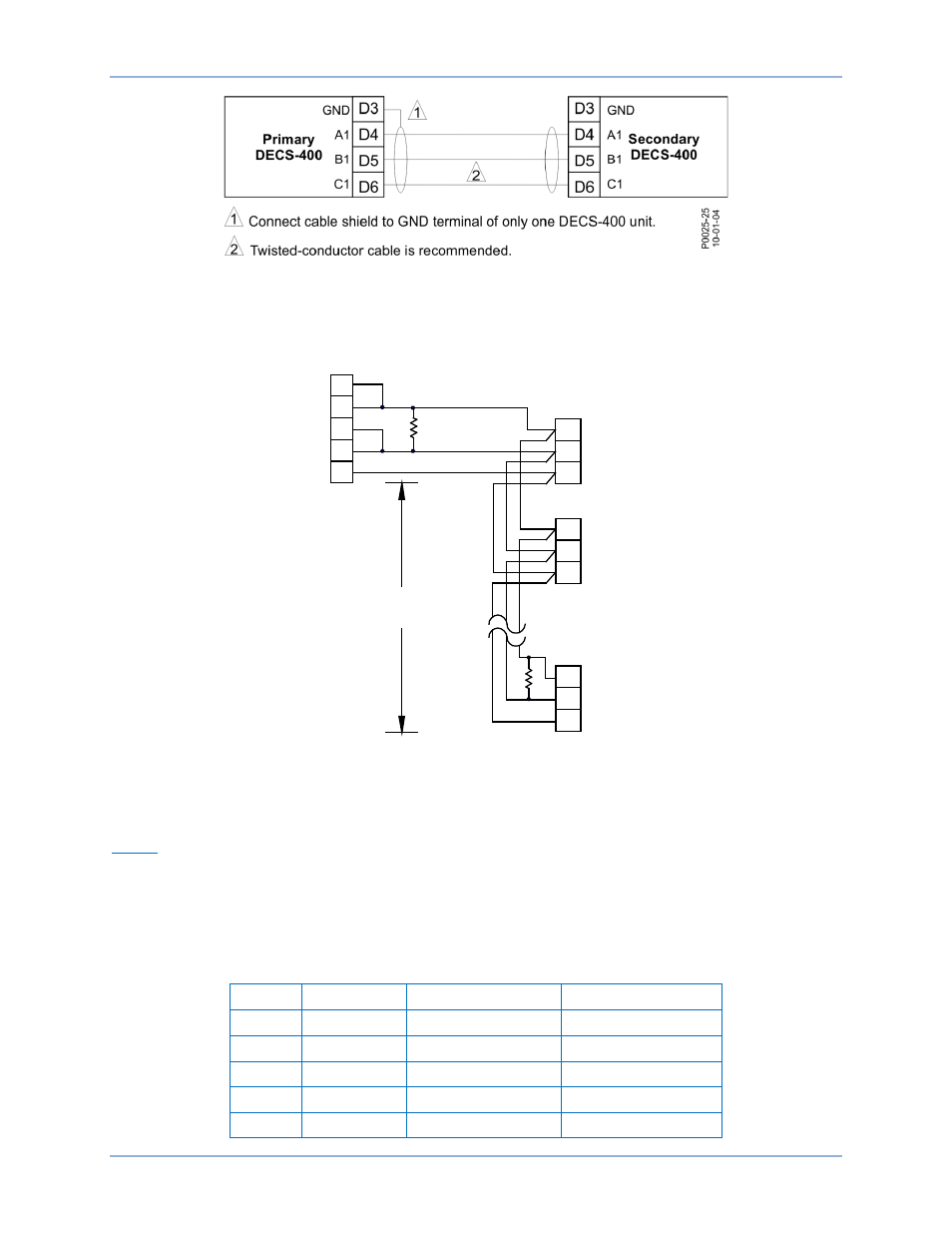
Figure 97. Com 1 Connections for Redundant DECS-400 Operation
Figure 98 illustrates the Com 2 connections used for multiple DECS-400 units communicating over a
Modbus network.
Figure 98. DECS-400 to RS-485 DB-37 Connections
Com 3
Com 3 is used for 10BASE-T Ethernet network communication. The Com 3 jack accepts an eight pin, RJ-
45 plug connected to unshielded, twisted-pair, Category 5 copper conductors. Conductor length, per
segment, can be no longer than 100 meters or 328 feet. Com 3 has a maximum data transfer rate of 10
megabits per second. Pin assignments/definitions for the Com 3 connector are listed in Table 20 and
illustrated in Figure 99.
Table 20. Com 3 Connector Pin Definitions
Pin
Signal
Function
Direction
1
TD+
Transmit data +
From DECS-400
2
TD–
Transmit data –
From DECS-400
3
RD+
Receive data +
To DECS-400
4
Not used
5
Not used
P
0026-
01
10-
01-
04
22
6
4
D9
To DECS-400
Com 2
To RS-422/RS-485
DB-37 Female
19
24
4000' (1219 m)
maximum
DECS-400
Com 2
R
t
t
R
R
t
= Optional terminating
resistor (120 ohms typ.)
A2
B2
C2
D10
D11
D9
DECS-400
Com 2
A2
B2
C2
D10
D11
D9
DECS-400
Com 2
A2
B2
C2
D10
D11
DECS-400
Installation