Basler Electric DECS-400 User Manual
Page 95
9369700990 Rev R
83
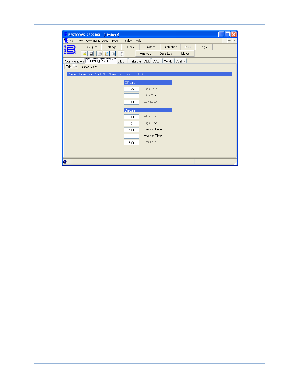
Figure 48. Limiters Screen, Summing Point OEL Tab
On-Line – High Level. This setting configures the high-level current setpoint for the summing point on-line
overexcitation limiter. A setting of 0 to 11,999 Adc may be entered in 0.01 Adc increments.
On-Line – High Time. This setting establishes the time limit for high current limiting by the summing point
on-line overexcitation limiter. A setting of 0 to 240 seconds may be entered in 1 second increments.
On-Line – Medium Level. This setting configures the medium-level current setpoint for the summing point
on-line overexcitation limiter. A setting of 0 to 11,999 Adc may be entered in 0.01 Adc increments.
On-Line – Medium Time. This setting establishes the time limit for medium current limiting by the
summing point on-line overexcitation limiter. A setting of 0 to 240 seconds may be entered in 1 second
increments.
On-Line – Low Level . This setting configures the low-level current setpoint for the summing point on-line
overexcitation limiter. A setting of 0 to 11,999.00 Adc may be entered in 0.01 Adc increments.
UEL
The UEL tab has two setting groups: Primary and Secondary. The Primary and Secondary buttons select
between the primary and secondary Underexcitation Limiter settings. In the default logic schemes
provided with the DECS-400, a contact input is used to select either the primary or secondary UEL
settings.
UEL functions are shown in Figure 49 and described in the following paragraphs.
Curve Selection. This setting selects either a custom or internal underexcitation limiter curve and is
enabled in all DECS-400 operating modes except FCR. Selecting Custom enables the user to configure a
customized, one-to-five point UEL curve that matches a specific generator’s characteristics. Selecting
Internal creates a UEL curve based on the first point setting of the absorbed reactive power level.
Real Power (kW). These setting fields establish the real-power points of the underexcitation limiter
curves. Depending on whether a three-point or five-point curve is selected, either three or five setting
fields are enabled to accept point values. The Curve Selection setting must be “Custom” in order for these
setting fields to be enabled. The range for each setting field is based on the generator ratings entered on
the Rated Data tab of the System Configuration screen.
DECS-400
BESTCOMS™ Software