Basler Electric DECS-400 User Manual
Page 131
9369700990 Rev R
119
provided to return the FVR setpoint to its original value before any step changes were invoked. This
original value is the FVR setpoint entered on the AVR/FCR/FVR tab of the BESTCOMS Settings screen
and is displayed in the read-only field adjacent to the button.
A checkbox enables the triggering of a data log when a step change is initiated.
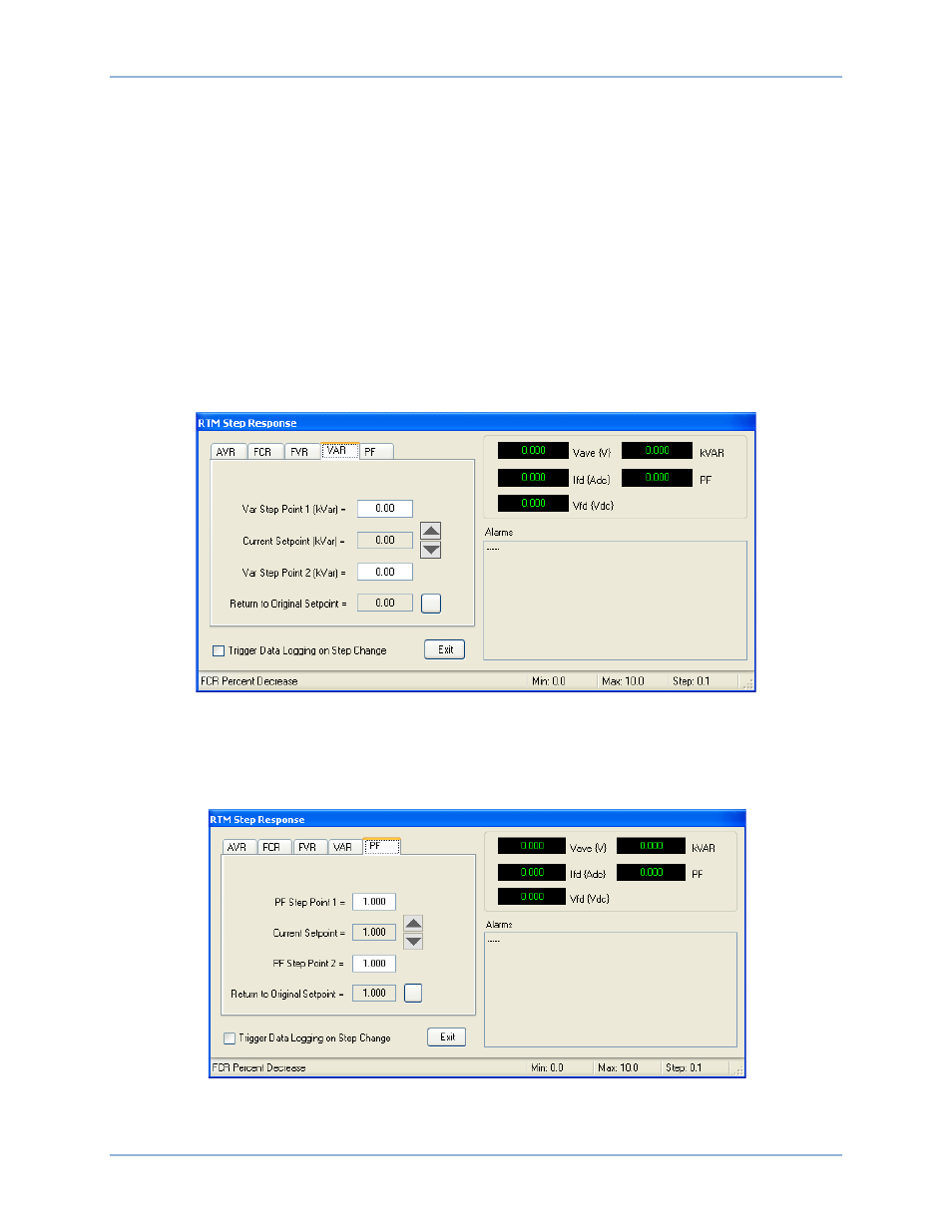
VAR Tab
VAR tab functions are shown in Figure 85 and described in the following paragraphs.
The VAR tab of the RTM Step Response screen enables step changes to be applied to the kvar setpoint.
Two user-adjustable step changes are available for the kvar setpoint: Var Step Point 1 and Var Step Point
2. The Var Step Point 1 value is selected by clicking the increment (up arrow) button and the Var Step
Point 2 value is selected by clicking the decrement (down arrow) button. The acceptable setting range for
each step point is determined by the var minimum and maximum settings entered on the VAR/PF tab of
the BESTCOMS Settings screen. A read-only field displays the current reactive power setpoint. A button
is provided to return the var setpoint to its original value before any step changes were invoked. This
original value is the var setpoint entered on the VAR/PF tab of the BESTCOMS Settings screen and is
displayed in the read-only field adjacent to the button.
Figure 85. RTM Step Response Screen, VAR Tab
A checkbox enables the triggering of a data log when a step change is initiated.
PF Tab
PF tab functions are shown in Figure 86 and described in the following paragraphs.
Figure 86. RTM Step Response Screen, PF Tab
The PF tab of the RTM Step Response screen enables step changes to be applied to the power factor
setpoint. Two user-adjustable step changes are available for the power factor setpoint: PF Step Point 1
DECS-400
BESTCOMS™ Software