Verify and finalize modified logic scheme, Logic for compound machine paralleling – Basler Electric DECS-400 User Manual
Page 204
192
9369700990 Rev R
Verify and Finalize Modified Logic Scheme
Logic scheme modifications can be verified by reviewing the logic associations displayed in the DECS
Logic Viewer.
If desired, the relay output labels (accessed through the I/O Status tab of the BESTCOMS Metering
screen) can be edited to reflect their changed functionality. See the BESTCOMS Software chapter for
information about changing I/O label assignments.
Logic for Compound Machine Paralleling
The following logic modification instructions are provided for applications where the DECS-400 will control
a compound machine. These instructions can be used to modify any one of the four default logic scheme
files: Single DECS-400 Without PSS, Single DECS-400 With PSS, Dual DECS-400 Without PSS, or Dual
DECS-400 With PSS. Modifying one of the default logic schemes forces the DECS-400 to always operate
in parallel. Voltage matching and (online and offline) OEL settings are toggled based on the status of
switch input 3 (52b). Perform the following steps to modify the DECS-400 logic for compound machine
paralleling.
1.
Select the desired, default logic scheme for modification. In BESTCOMS, click File, open Default
Scheme… and click the button labeled with the desired logic scheme.
2.
Access the DECS Logic window by clicking the Logic button on the BESTCOMS toolbar.
3.
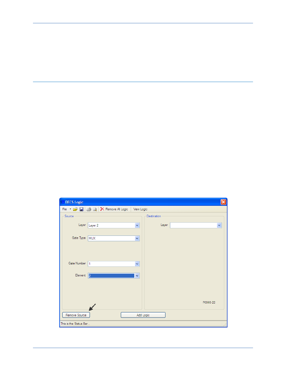
Figure 129 illustrates the DECS Logic window settings associated with this step. In the Source portion
of the DECS Logic window:
a.
Select Layer 2 from the Layer pull-down menu.
b.
Select MUX as the Gate Type.
c.
Select 1 as the Gate Number.
d.
Select 2 as the Element.
e.
Click the Remove Source button.
Figure 129. Disconnect Layer 2 Multiplexor 1, Output 2
Programmable Logic
DECS-400