Basler Electric DECS-400 User Manual
Page 90
78
9369700990 Rev R
When tuning the proportional gain, consider the following guidelines. If the transient response has too
much overshoot, then Kp should be decreased. If the transient response is too slow, with little or no
overshoot, then Kp should be increased.
AVR – Ki-Integral Gain. This setting selects the integral constant (Ki) stability parameter. The DECS-400
provides an output value that is equivalent to Ki multiplied by the integral of the error between the voltage
setpoint and the actual generator output voltage. A setting of 0 to 1,000.0 may be entered in increments
of 0.1. This setting is enabled only when Custom is selected as the Primary Gain Option of the PID Pre-
Settings.
If the time to reach steady-state is deemed too long, then Ki should be increased.
AVR – Kd-Derivative Gain. This setting selects the derivative constant (Kd) stability parameter. The
DECS-400 provides an output value that is equivalent to Kd multiplied by the derivative of the error
between the voltage setpoint and the actual generator output voltage. A setting of 0 to 1,000.0 may be
entered in increments of 0.1. This setting is enabled only when Custom is selected as the Primary Gain
Option of the PID Pre-Settings.
If the transient response has too much ringing, then Kd should be increased.
AVR – Td-AVR Derivative Time Constant. This setting is used to remove the noise effect on numerical
differentiation. A setting of 0 to 1.00 may be entered in increments of 0.01.
AVR – Kg-AVR Loop Gain. This setting adjusts the coarse loop-gain level of the PID algorithm for AVR
mode. A setting of 0 to 1,000.0 may be entered in increments of 0.1.
PID Pre-Settings – Primary Gain Option. This drop-down menu lists 20 predefined gain settings and an
option for selecting custom PID settings. The predefined gain settings listed depend on whether Main
Field or Exciter Field is selected as the Field Type (System Configuration screen, Options tab). Selecting
Custom in the drop-down menu enables the PID Calculator button.
PID Calculator Button. Clicking this button opens the PID Calculator shown in Figure 43. Note that a PID
Calculator exists for primary gain settings and secondary gain settings. The PID Calculator opened by the
PID Calculator button depends on whether the Primary or Secondary button is selected on the AVR Gain
tab.
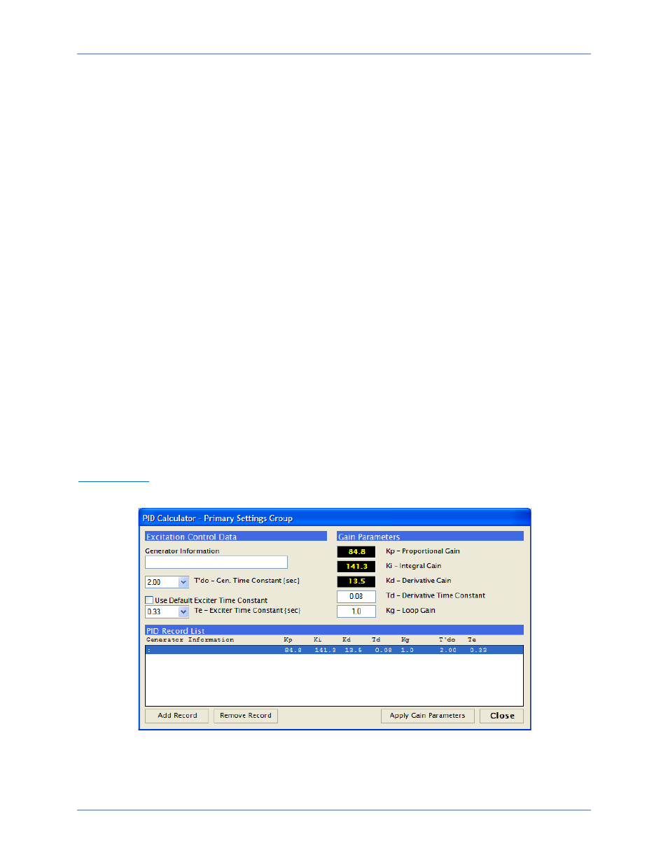
PID Calculator
PID Calculator functions are shown in Figure 44 and described in the following paragraphs.
Figure 44. PID Calculator
Excitation Control Data – Generator Information. This setting field is used to enter and display a
descriptive name for the selected group of PID settings. The Generator Information field accepts up to 30
alphanumeric characters.
BESTCOMS™ Software
DECS-400