Create new logic associations – Basler Electric DECS-400 User Manual
Page 201
Advertising
9369700990 Rev R
189
Create New Logic Associations
After all unneeded logic associations are deleted, new logic associations can be made. Table A-2 lists the
logic of the modified scheme after all deletions and additions have been made. Bold entries in the list
indicate logic associations that will be added here.
1.
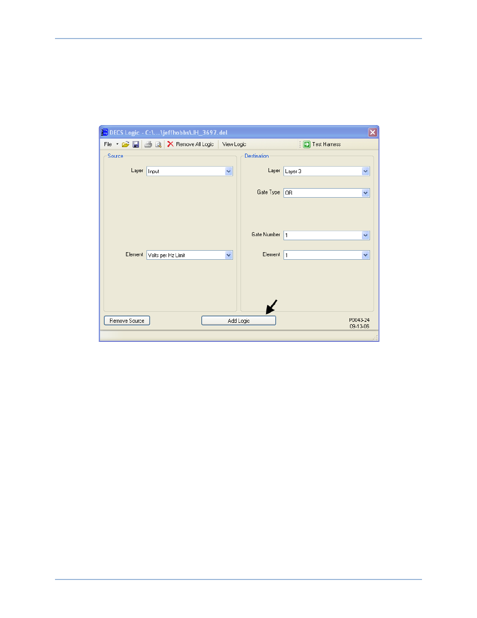
Figure 124 illustrates the DECS Logic window settings associated with this step. Connect the V/Hz
Protection Active input buffer to input 1 of OR gate 1 on logic layer 3. In Table 24, this association is
identified by “DESTINATION: Layer3 – InputBuffer.Volts per Hz Limit
Or1.Input1”.
Figure 124. Addition of Layer3 InputBuffer.Volts per Hz Limit ---> Layer3.Or1.Input1
DECS-400
Programmable Logic
Advertising