Basler Electric DECS-400 User Manual
Page 78
66
9369700990 Rev R
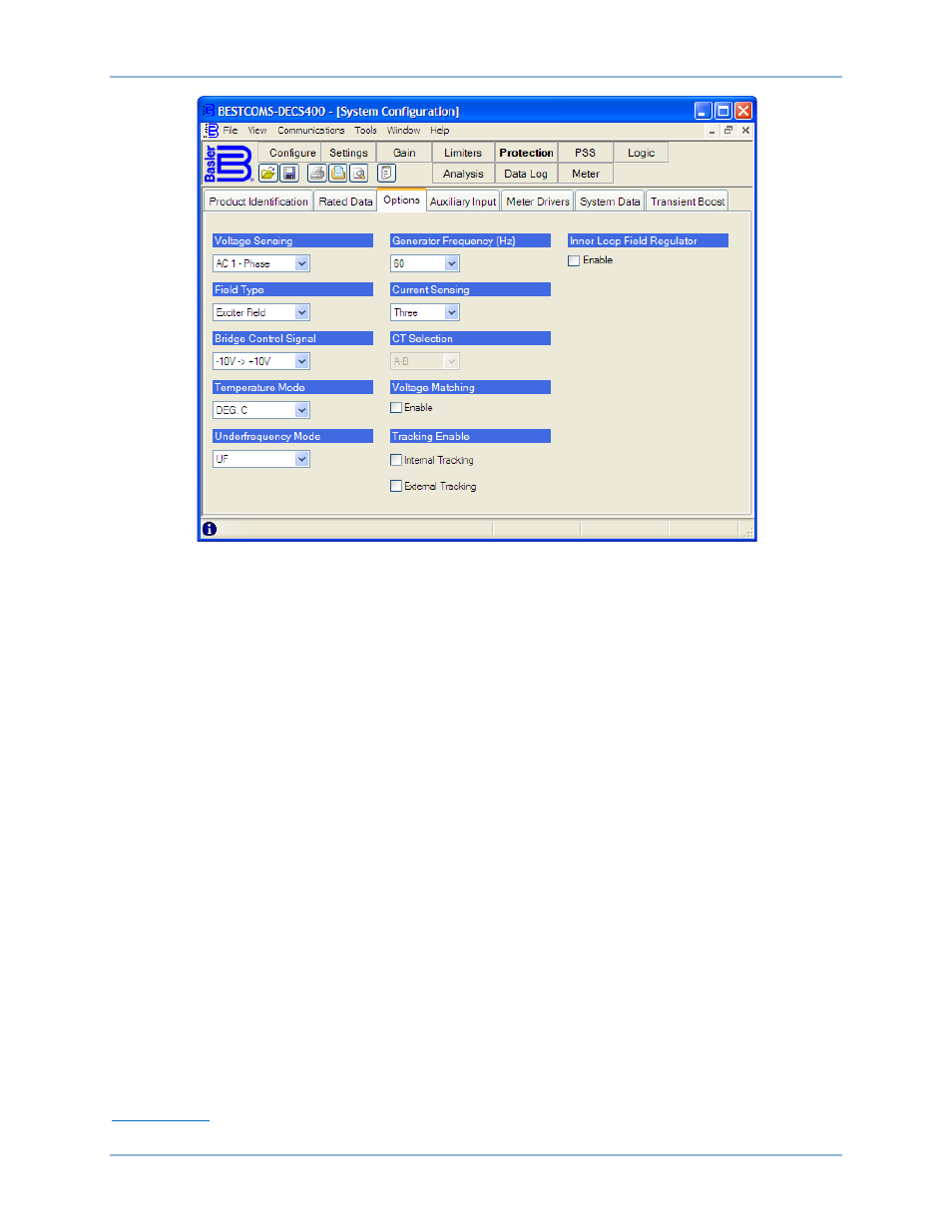
Figure 35. System Configuration Screen, Options Tab
Temperature Mode. This setting determines the scale that BESTCOMS and the DECS-400 front panel
HMI uses to display the field temperature and the overtemperature alarm level. The temperature mode is
selected from the drop-down menu. DEG. C selects the Celsius temperature scale and DEG. F selects
the Fahrenheit temperature scale.
Underfrequency Mode. This setting selects either underfrequency limiting (UF) or volts per hertz (V/Hz)
limiting. The underfrequency mode is selected from the drop down menu.
Generator Frequency (Hz). This setting selects the nominal system operating frequency as 50 hertz or 60
hertz. The generator frequency is selected from the drop-down menu.
Current Sensing. This setting selects the number of phases used for sensing generator current. The
current sensing configuration is selected from the drop-down menu and may be set at one, two, or three
phases.
CT Selection. This setting is enabled only when the Current Sensing setting is “Two”. The drop-down
menu is used to select which two generator phases are used to supply current sensing to the DECS-400.
Phases A-B, B-C, or A-C may be selected.
Voltage Matching. This setting enables and disables matching of the generator voltage to the bus voltage.
For voltage matching to occur, the DECS-400 must be in AVR mode, var and power factor modes must
be disabled, and the system off line.
Tracking Enable. This setting enables and disables internal tracking and external tracking. Selecting
Internal Tracking enables the inactive control modes to track the setpoint of the active control mode.
When used as a secondary DECS-400 in a redundant DECS-400 system, selecting External Tracking
enables the DECS-400 to track the active setpoint of the primary DECS-400.
Inner Loop Field Regulator. This setting enables the inner control loop of the field regulator for
compensation of the exciter gains and time constants. When the inner control loop is enabled, the
regulator response is dependent upon the inner loop gains selected on the Other Gain tab of the Gain
Settings screen.
Auxiliary Input
Auxiliary Input tab functions are shown in Figure 36 and described in the following paragraphs.
BESTCOMS™ Software
DECS-400