Basler Electric DECS-400 User Manual
Page 88
76
9369700990 Rev R
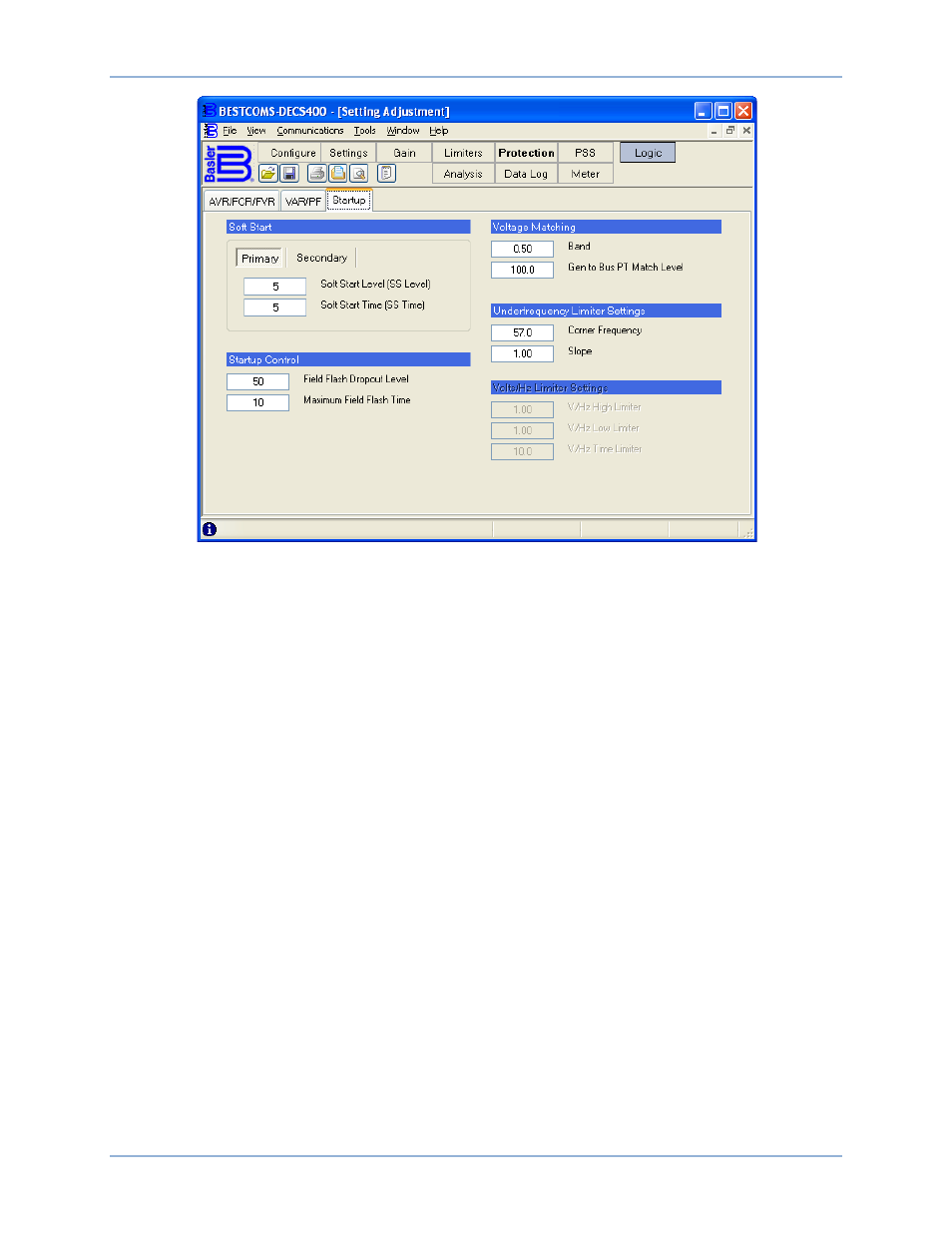
Figure 42. Setting Adjustment Screen, Startup Tab
The Primary and Secondary buttons select between the primary and secondary Soft Start settings. In the
default, non-PSS logic schemes provided with the DECS-400, a contact input is used to select either the
primary or secondary Soft Start settings.
Startup Control – Field Flash Dropout Level. During startup, this setting controls the level of generator
voltage where field flashing is withdrawn. The Field Flash Dropout Level setting is expressed as a
parentage of the nominal generator terminal voltage. A setting of 0 to 100 percent may be entered in 1
percent increments.
Startup Control – Maximum Field Flash Time. This setting dictates the maximum length of time that field
flashing may be applied during startup. A setting of 1 to 50 seconds may be entered in 1-second
increments.
Voltage Matching – Band. This setting configures the generator voltage matching band as a percentage
of the generator rated voltage. When the bus input voltage falls outside this band, no voltage matching
occurs. A setting of 0 to 20.00 percent may be entered in .01 percent increments.
Voltage Matching – Gen to Bus PT Match Level. This setting ensures accurate voltage matching by
compensating for the error between the generator and bus voltage sensing transformers. The Match
Level is expressed as the relationship of the generator voltage to the bus voltage (expressed as a
percentage). A setting of 90 to 120.0 percent may be entered in 0.1 percent increments.
Underfrequency Settings – Corner Frequency. The generator corner frequency for generator
underfrequency and volts per hertz protection is entered in this field. A setting of 15 to 90 hertz may be
entered in 0.1 hertz increments.
Underfrequency Settings – Slope. The generator frequency slope for generator underfrequency and volts
per hertz protection is entered in this field. A per-unit value of 0 to 3.00 may be entered in 0.01
increments.
Volts/Hz Limiter Settings – V/Hz High Limiter. This per unit setting establishes the maximum threshold for
the volts per hertz limiter. A setting of 0 to 3.00 may be entered in 0.01 increments.
Volts/Hz Limiter Settings – V/Hz Low Limiter. This per unit setting establishes the minimum threshold for
the volts per hertz limiter. A setting of 0 to 3.00 may be entered in 0.01 increments.
BESTCOMS™ Software
DECS-400