Logic schemes, Default logic scheme, Predefined logic schemes – Basler Electric DECS-400 User Manual
Page 182: Timer
170
9369700990 Rev R
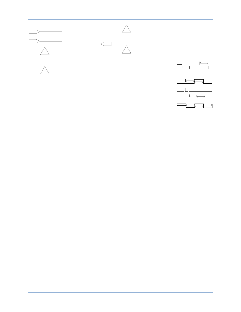
Figure 105. Logic Timer Configuration
Logic Schemes
Logic schemes provided with the DECS-400 include a default scheme that is part of the DECS-400
default settings and four predefined schemes supplied as files with the DECS-400.
Default Logic Scheme
A basic logic scheme is provided as part of the DECS-400 default settings. This scheme automatically
selects either on-line or off-line overexcitation limiting and disables voltage matching during off-line
operation. The default logic scheme is illustrated in Figure 106.
Predefined Logic Schemes
The predefined schemes are supplied as files that are loaded on your PC when BESTCOMS is installed.
A scheme can be accessed through the “Open Default Scheme…” command of the BESTCOMS File
menu. If desired, a logic scheme may be opened and modified to accommodate the specific requirements
of your application. If modification of a logic scheme is desired, contact the Basler Electric Technical
Services Department for assistance.
Four predefined logic schemes are supplied with BESTCOMS for the DECS-400. These schemes include
common control and annunciation provisions for the following applications:
•
Single DECS-400 system with power system stabilization (PSS)
•
Single DECS-400 system without PSS
•
Dual DECS-400 system with PSS
•
Dual DECS-400 system without PSS
The logic scheme for a single DECS-400 with PSS is illustrated in Figures 107, 108, and 109. Figures
110, 111, and 112 illustrate the logic scheme for a single DECS-400 without PSS. The logic scheme for a
dual DECS-400 with PSS is illustrated in Figures 113, 114, and 115. Figures 116, 117, and 118 illustrate
the logic scheme for a dual DECS-400 without PSS.
TIMER
Mode
T1
T2
Input
Output
Element 1
Element 2
Block
Inhibit
T1
T2
P
0
0
7
3
-0
1
1
1
Timer mode is Disabled, Pickup/Dropout, One Shot
Non-Retriggerable, One Shot Retriggerable, or
Oscillator.
2
2
Timer output response to an input is illustrated as
follows for each timer mode.
Pickup/Dropout
One-Shot Non-
Retriggerable
One-Shot
Retriggerable
Oscillator
Input
Output
T1
T2
Output
Input
T1
T2
Output
Input
T2
T1
T2
T1
Output
Programmable Logic
DECS-400