Yaskawa J1000 Compact Vector Control Drive User Manual
Page 102
The table below shows how to set up the drive when using output terminals P2-PC as brake
control output.
Brake Open/Close
Brake Activation Level
Control Mode
Function
Parameter
Signal
Parameter
V/f
OLV
OLV
for PM
Frequency
Detection 2
L4-07 = 0
Frequency Detection Level
L4-01 = 1.0 to 3.0 Hz
<1>
O
O
−
H2-03 = 5
Frequency Detection Width
L4-02 = 0.0 to 0.5 Hz
<2>
<1>
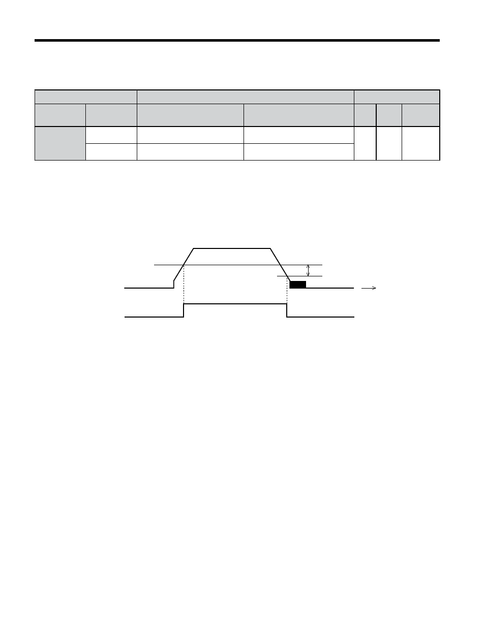
This is the setting recommended when using Open Loop Vector Control. In V/f Control, set the level as the
motor rated slip frequency plus 0.5 Hz. Not enough motor torque will be created if this value is set too low, and
the load may tend to slip. Make sure this value is greater than the minimum output frequency and greater than
the value of L4-02 as shown in the diagram below. If set too high, however, there may be a jolt at start.
<2>
Hysteresis for Frequency Detection 2 can be adjusted by changing the Frequency Detection Width (L4-02)
between 0.0 and 0.5 Hz. If the load slips during stop, make changes in steps of 0.1 Hz until the load no longer
slips.
L4-02
L4-01
OFF
ON
Time
Output
frequency
Frequency
detection 2
Figure 4.8 Frequency Detection 2
The braking sequence should be designed as follows:
• A normally open signal (N.O.) should be used to control the brake so that it is released
when terminal P2-PC closes.
• When an Up or Down command is entered, the brake should release.
• When a fault signal is output, the brake should close.
• When changing the speed using an analog signal, make sure that the source of the frequency
reference is assigned to the control circuit terminals (b1-01 = 1).
• A sequence to open and close the holding brake appears in the diagram below.
4.5 Application Selection
102
YASKAWA ELECTRIC TOEP C710606 47C YASKAWA AC Drive – V1000 Quick Start Guide