B.1 parameter table – Yaskawa J1000 Compact Vector Control Drive User Manual
Page 204
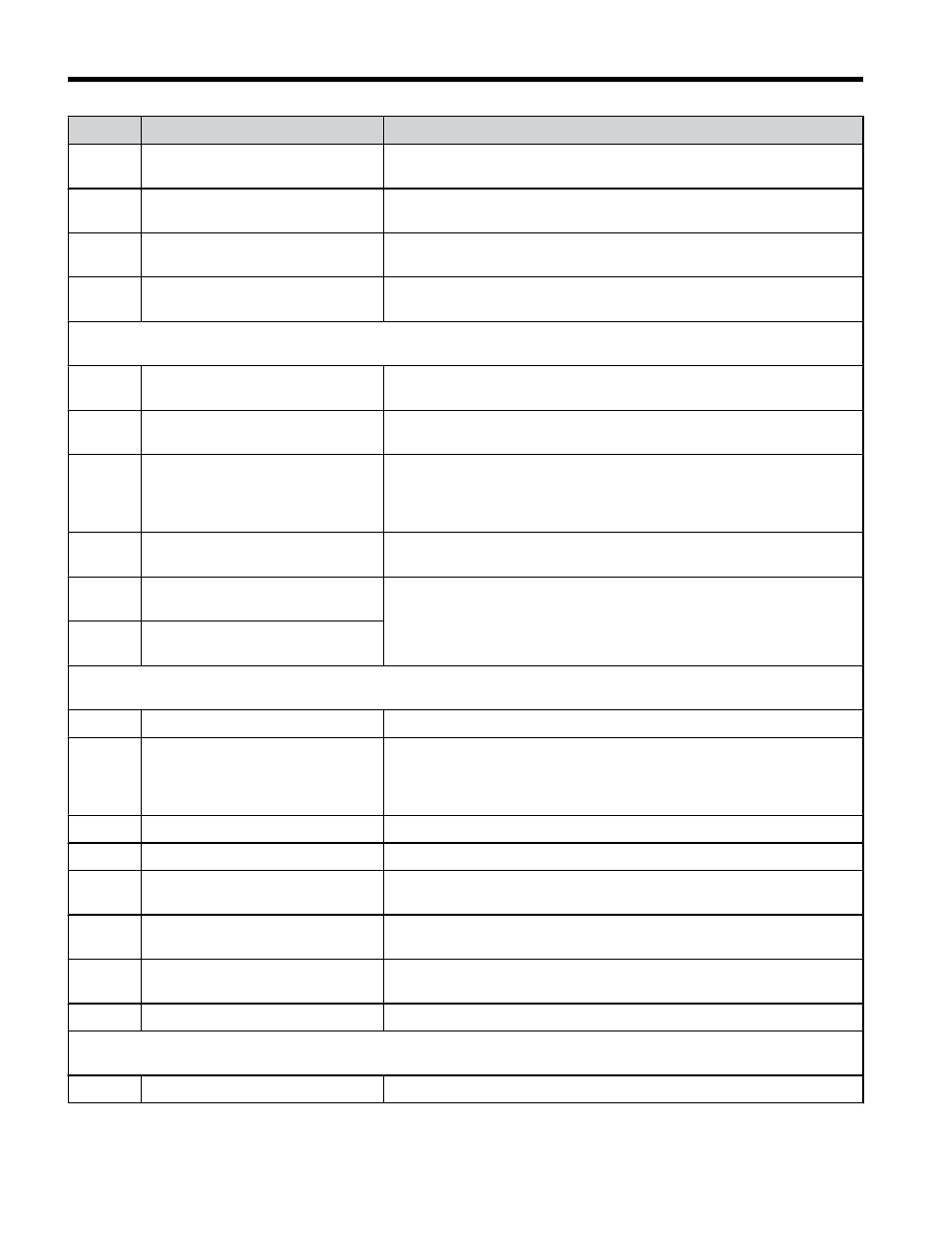
No.
Name
Description
n8-88
Output Voltage Limit Switching
Current Level
Refer to V1000 Technical Manual for details.
Note: Available in drive software versions PRG: 1018 and later.
n8-89
Output Voltage Limit Switching
Current Hysteresis Width
Refer to V1000 Technical Manual for details.
Note: Available in drive software versions PRG: 1018 and later.
n8-90
Output Voltage Limit Switching
Speed
Refer to V1000 Technical Manual for details.
Note: Available in drive software versions PRG: 1018 and later.
n8-91
Id Limit for Output Voltage Limit
Control
Refer to V1000 Technical Manual for details.
Note: Available in drive software versions PRG: 1018 and later.
o1: Display Settings
Use o1 parameters to configure the digital operator display.
o1-01
Drive Mode Unit Monitor
Selection
Refer to V1000 Technical Manual for details.
o1-02
User Monitor Selection After
Power Up
Refer to V1000 Technical Manual for details.
o1-03
Digital Operator Display Selection
0: Hz
1: % (100% = E1-04)
2: r/min (enter the number of motor poles into E2-04/E4-04/E5-04)
3: User defined by parameters o1-10 and o1-11
o1-05
LCD Contrast Control
Refer to V1000 Technical Manual for details.
Note: Available in drive software versions PRG: 1022 and later.
o1-10
Frequency Reference Setting and
User-Set Display
Refer to V1000 Technical Manual for details.
o1-11
Frequency Reference Setting /
Decimal Display
o2: Multi-Function Selections
Use o2 parameters to configure LED digital operator key functions.
o2-01
LO/RE Key Function Selection
Refer to V1000 Technical Manual for details.
o2-02
STOP Key Function Selection
Enables/Disables the operator panel STOP key when the drive is
operated form external sources (not operator).
0: Disabled.
1: Enabled
o2-03
User Parameter Default Value
Refer to V1000 Technical Manual for details.
o2-04
Drive Model Selection
Refer to V1000 Technical Manual for details.
o2-05
Frequency Reference Setting
Method Selection
0: Data/Enter key must be pressed to enter a frequency reference.
1: Data/Enter key is not required.
o2-06
Operation Selection when Digital
Operator is Disconnected
0: The drive will continue operation
1: The drive will trigger a fault (oPr) and the motor will coast to stop
o2-07
Motor Direction at Power Up when
Using Operator
Refer to V1000 Technical Manual for details.
o2-09
–
Factory use
o3: Copy Function
Use o3 parameters to Read, Copy and Verify the parameter settings to and from the drive.
o3-01
Copy Function Selection
Refer to V1000 Technical Manual for details.
B.1 Parameter Table
204
YASKAWA ELECTRIC TOEP C710606 47C YASKAWA AC Drive – V1000 Quick Start Guide