8 wiring checklist – Yaskawa J1000 Compact Vector Control Drive User Manual
Page 80
No.
Item
Page
14
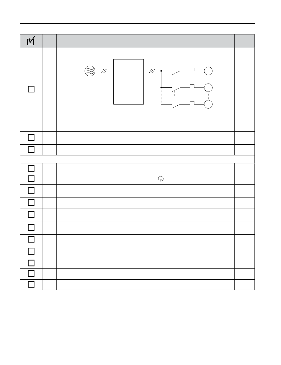
Set up overload protection circuits when running multiple motors from a single drive.
M1
OL1
OL2
OLn
MC1
MC2
MCn
M2
Mn
Drive
MC1 - MCn
OL 1 - OL n
... magnetic contactor
... thermal relay
Power supply
Note: Close MC1 through MCn before operating the drive.
–
15
If using a braking resistor or dynamic braking resistor unit, install a magnetic contactor.
Properly install the resistor, and ensure that overload protection shuts off the power supply.
–
16
Verify phase advancing capacitors are NOT installed on the output side of the drive.
–
Control circuit wiring
17
Use twisted-pair cables for all drive control circuit wiring.
18
Ground the shields of shielded wiring to the GND terminal.
19
If using a 3-Wire sequence, properly set parameters for multi-function contact input
terminals S1 through S7, and properly wire control circuits.
20
Properly wire any option cards.
–
21
Check for any other wiring mistakes.
Only use a multimeter to check wiring.
–
22
Properly fasten the control circuit terminal screws in the drive. Refer to
23
Pick up all wire clippings.
–
24
Ensure that no frayed wires on the terminal block are touching other terminals or
connections.
–
25
Properly separate control circuit wiring and main circuit wiring.
–
26
Analog signal line wiring should not exceed 50 m.
–
27
Safe Disable Input wiring should not exceed 30 m.
–
3.8 Wiring Checklist
80
YASKAWA ELECTRIC TOEP C710606 47C YASKAWA AC Drive – V1000 Quick Start Guide