B.1 parameter table – Yaskawa J1000 Compact Vector Control Drive User Manual
Page 208
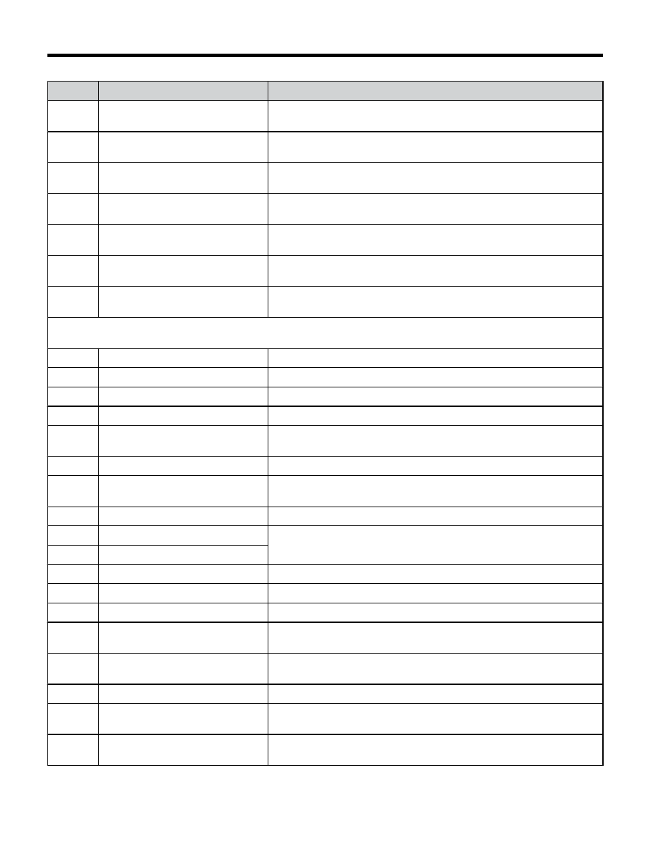
No.
Name
Description
U3-14 Cumulative Operation Time at 4th
Most Recent Fault
Displays the cumulative operation time at the fourth most recent fault.
U3-15 Cumulative Operation Time at 5th
Most Recent Fault
Displays the cumulative operation time at the fifth most recent fault.
U3-16 Cumulative Operation Time at 6th
Most Recent Fault
Displays the cumulative operation time at the sixth most recent fault.
U3-17 Cumulative Operation Time at 7th
Most Recent Fault
Displays the cumulative operation time at the seventh most recent fault.
U3-18 Cumulative Operation Time at 8th
Most Recent Fault
Displays the cumulative operation time at the eighth most recent fault.
U3-19 Cumulative Operation Time at 9th
Most Recent Fault
Displays the cumulative operation time at the ninth most recent fault.
U3-20 Cumulative Operation Time at
10th Most Recent Fault
Displays the cumulative operation time at the tenth most recent fault.
U4: Maintenance Monitors
Use U4 parameters to display drive maintenance information.
U4-01 Accumulated Operation Time
Refer to V1000 Technical Manual for details.
U4-02 Number of Run Commands
Refer to V1000 Technical Manual for details.
U4-03 Cooling Fan Operation Time
Refer to V1000 Technical Manual for details.
U4-05 Capacitor Maintenance
Refer to V1000 Technical Manual for details.
U4-06 Soft Charge Bypass Relay
Maintenance
Refer to V1000 Technical Manual for details.
U4-07 IGBT Maintenance
Refer to V1000 Technical Manual for details.
U4-08 Heatsink Temperature
Refer to V1000 Technical Manual for details.
Note: Available in drive software versions PRG: 1011 and later.
U4-09 LED Check
Refer to V1000 Technical Manual for details.
U4-10 kWH, Lower 4 Digits
Monitors the drive output power.
U4-11 kWH, Upper 5 Digits
U4-13 Peak Hold Current
Displays the peak hold current during run.
U4-14 Peak Hold Output Frequency
Refer to V1000 Technical Manual for details.
U4-16 Motor Overload Estimate (OL1)
100% = OL1 detection level
U4-18 Frequency Reference Source
Selection
Refer to V1000 Technical Manual for details.
U4-19 Frequency Reference from
MEMOBUS/Modbus Comm.
Refer to V1000 Technical Manual for details.
U4-20 Option Frequency Reference
Refer to V1000 Technical Manual for details.
U4-21
Run Command Source Selection
Refer to V1000 Technical Manual for details.
U4-22 MEMOBUS/Modbus
Communications Reference
Refer to V1000 Technical Manual for details.
B.1 Parameter Table
208
YASKAWA ELECTRIC TOEP C710606 47C YASKAWA AC Drive – V1000 Quick Start Guide