Run command input selection: b1-02, For more information on a 2-wire and 3 – Yaskawa J1000 Compact Vector Control Drive User Manual
Page 109
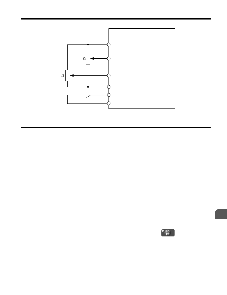
Drive
A1
A2
Main Frequency Reference
(voltage input)
Aux Frequency Reference 1
AC
S5
Frequency Reference Common
Multi-Function Digital Input
SC Digital Input Common
+ V (+10.5 V, 20 mA)
2 k
(voltage input)
2 k
Figure 4.11 Switching between Main/Auxiliary Frequency References
u
Run Command Input Selection: b1-02
This section explains how to assign the run command input.
Parameters b1-01 and b1-02 can be used to select the source of the run command and the
frequency reference independently, e.g. set the reference from the operator and set the run
command from the terminals.
WARNING! Sudden Movement Hazard. When the run command is given by turning on the power to the drive,
the motor will begin rotating as soon as the drive is powered up. Be sure to take proper precautions if using
this setting. Ensure the area around the motor is safe. Failure to comply could result in death or serious injury.
n
Run the Drive at 6 Hz using the Digital LED Operator: b1-02 = 0
To assign the run command to the operator panel, set parameter b1-01 to “0”. This will set up
the drive to acknowledge the run command through the LED operator. Initialize the run
command using the Run and Stop keys. Upon power up, the drive uses parameter b1-02 to
determine the run command location.
The following procedure indicates how to start and stop the drive through the LED operator
after parameter b1-02 has been set to 0.
Note:
When b1-02 (Run Command Selection) is not set to 0 (operator), press
to set LOCAL.
4.6 Basic Drive Setup Adjustments
YASKAWA ELECTRIC TOEP C710606 47C YASKAWA AC Drive – V1000 Quick Start Guide
109
4
Start-Up Programming & Operation