2 fault detection – Yaskawa J1000 Compact Vector Control Drive User Manual
Page 138

Digital Operator Display
Fault Name
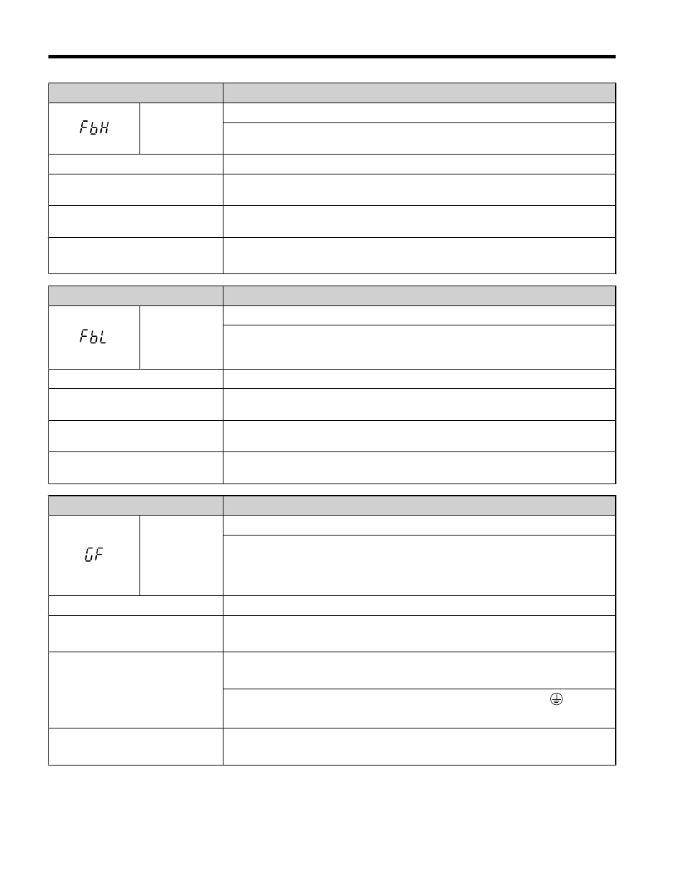
FbH
Excessive PID Feedback
PID feedback input is greater than the level set b5-36 for longer than the time set
to b5-37. Set b5-12 to 2 or 5 to enable fault detection.
Cause
Possible Solution
Parameters are not set
appropriately.
Check the settings of parameters b5-36 and b5-37.
Wiring for PID feedback is
incorrect.
Correct the wiring.
There is a problem with the
feedback sensor.
• Check the sensor on the control side.
• Replace the sensor if damaged.
Digital Operator Display
Fault Name
FbL
PID Feedback Loss
This fault occurs when PID Feedback Loss Detection is programmed to fault
(b5-12 = 2) and the PID Feedback < PID Feedback Loss Detection Level (b5-13)
for the PID Feedback Loss Detection Time (b5-14).
Cause
Possible Solution
Parameters are not set
appropriately.
Check the settings of parameters b5-13 and b5-14.
Wiring for PID feedback is
incorrect.
Correct the wiring.
There is a problem with the
feedback sensor.
Check the sensor on the controller side. If damaged, replace the sensor.
Digital Operator Display
Fault Name
GF
Ground Fault
• Current shorted to ground exceeded 50% of rated current on output side of the
drive.
• Setting L8-09 to 1 enables ground fault detection in models 2A0020 to 2A0069
and 4A0011 to 4A0038.
Cause
Possible Solution
Motor insulation is damaged.
• Check the insulation resistance of the motor.
• Replace the motor.
A damaged motor cable is creating
a short circuit.
• Check the motor cable.
• Remove the short circuit and turn the power back on.
• Check the resistance between the cable and the ground terminal .
• Replace the cable.
The leakage current at the drive
output is too high.
• Reduce the carrier frequency.
• Reduce the amount of stray capacitance.
5.2 Fault Detection
138
YASKAWA ELECTRIC TOEP C710606 47C YASKAWA AC Drive – V1000 Quick Start Guide