2 fault detection – Yaskawa J1000 Compact Vector Control Drive User Manual
Page 146

Digital Operator Display
Fault Name
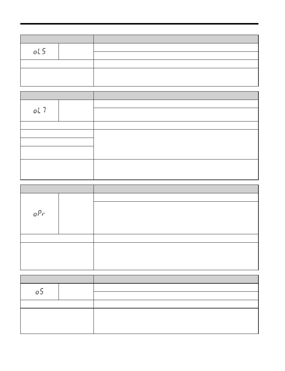
oL5
Mechanical Weakening Detection 1
Overtorque occurred, matching the conditions specified in L6-08.
Cause
Possible Solution
Overtorque occurred, triggering the
mechanical weakening level set to
L6-08.
Check for the cause of mechanical weakening.
Digital Operator Display
Fault Name
oL7
High-Slip Braking oL
The output frequency stayed constant for longer than the time set in n3-04 during
High-slip Braking.
Cause
Possible Solution
Excessive load inertia.
• Reduce deceleration times using parameters C1-02, C1-04, C1-06 and C1-08
in applications that do not use High-slip Braking.
• Use a braking resistor to shorten deceleration time.
Motor is driven by the load.
Something on the load side is
restricting deceleration.
The overload time during High-slip
Braking is too short.
• Increase parameter n3-04 (High-slip Braking Overload Time).
• Install a thermal relay and increase the parameter setting of n3-04 to the
maximum value.
Digital Operator Display
Fault Name
oPr
External Digital Operator Connection Fault
• The external operator has been disconnected from the drive.
Note: An oPr fault will occur when all of the following conditions are true:
• Output is interrupted when the operator is disconnected (o2-06 = 1).
• The run command is assigned to the operator
(b1-02 = 0 and LOCAL has been selected).
Cause
Possible Solution
External operator is not properly
connected to the drive.
• Check the connection between the operator and the drive.
• Replace the cable if damaged.
• Turn off the drive input power and disconnect the operator. Next reconnect the
operator and turn the drive input power back on.
Digital Operator Display
Fault Name
oS
Overspeed (Simple V/f with PG)
Pulse input (RP) indicates that motor speed feedback exceeded F1-08 setting.
Cause
Possible Solution
Overshoot or undershoot is
occurring.
• Adjust the gain by using the pulse train input parameters (H6-02 through
H6-05).
• Increase the settings for C5-01 (Speed Control Proportional Gain 1) and reduce
C5-02 (Speed Control Integral Time 1).
5.2 Fault Detection
146
YASKAWA ELECTRIC TOEP C710606 47C YASKAWA AC Drive – V1000 Quick Start Guide