5 control circuit wiring, Control circuit terminal block functions, Refer to – Yaskawa J1000 Compact Vector Control Drive User Manual
Page 68: Terminal board, Control circuit wiring, Input terminals
3.5
Control Circuit Wiring
u
Control Circuit Terminal Block Functions
Drive parameters determine which functions apply to the multi-function digital inputs (S1 to
S7), multi-function digital outputs (MA, MB), multi-function pulse inputs and outputs (RP,
MP) and multi-function photocoupler outputs (P1, P2). The default is called out next to each
terminal in
WARNING! Sudden Movement Hazard. Always check the operation and wiring of control circuits after being
wired. Operating a drive with untested control circuits could result in death or serious injury.
WARNING! Confirm the drive I/O signals and external sequence before starting test run. Setting parameter
A1-06 may change the I/O terminal function automatically from the factory setting.
. Failure to comply may result in death or serious injury.
n
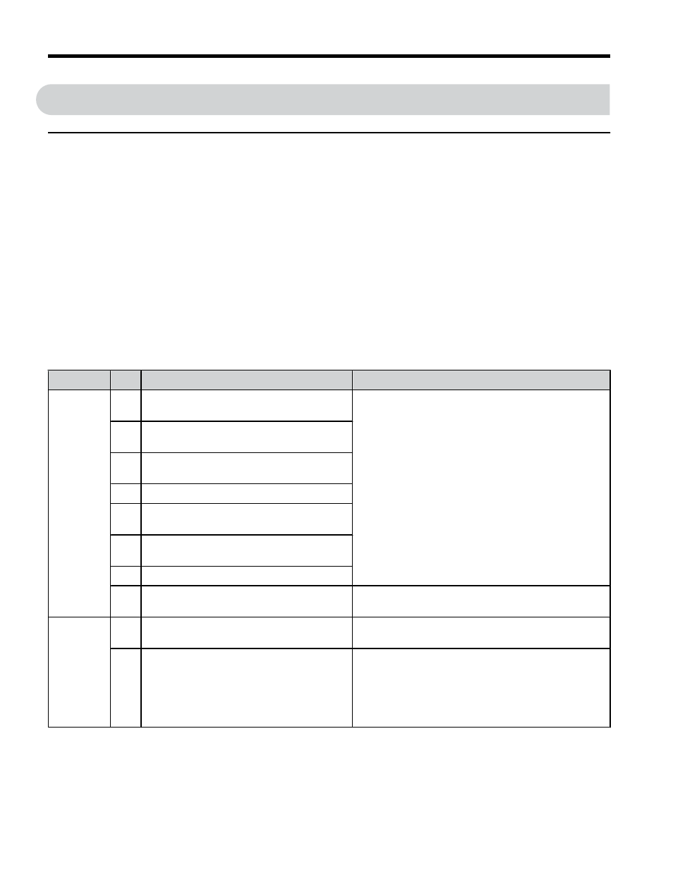
Input Terminals
Table 3.6 Control Circuit Input Terminals
Type
No.
Terminal Name (Function)
Function (Signal Level) Default Setting
Multi-
Function
Digital
Inputs
S1 Multi-function input 1 (Closed: Forward
run, Open: Stop)
Photocoupler
24 Vdc, 8 mA
Note: Drive preset to sinking mode. When using
source mode, set DIP switch S3 to allow for a 24 Vdc
(±10%) external power supply.
Sourcing Mode Switch on page 74
.
S2 Multi-function input 2 (Closed: Reverse
run, Open: Stop)
S3 Multi-function input 3 (External fault
(N.O.)
S4 Multi-function input 4 (Fault reset)
S5 Multi-function input 5 (Multi-step speed
reference 1)
S6 Multi-function input 6 (Multi-step speed
reference 2)
S7 Multi-function input 7 (Jog reference)
SC Multi-function input common (Control
common)
Sequence common
Safe
Disable
Input
HC Power supply for safe disable input
+24 Vdc (max 10 mA allowed)
Do not use external power supply.
H1 Safe disable input
Open: Output disabled
Closed: Normal operation
Note: Disconnect wire jumper between HC and H1
when using the safe disable input. The wire length
should not exceed 30 m.
Use only dry contacts on safety inputs HC-H1.
3.5 Control Circuit Wiring
68
YASKAWA ELECTRIC TOEP C710606 47C YASKAWA AC Drive – V1000 Quick Start Guide