Terminal configuration, Serial communication terminals, 5 control circuit wiring – Yaskawa J1000 Compact Vector Control Drive User Manual
Page 70
A
B
C
D
A – External power, 48 V max.
B – Suppression diode
C – Coil
D – 50 mA or less
Figure 3.14 Connecting a Suppression Diode
n
Serial Communication Terminals
Table 3.8 Control Circuit Terminals: Serial Communications
Type
No.
Signal Name
Function (Signal Level)
MEMOBUS/
Modbus
Communication
R+
Communications input (+)
MEMOBUS/Modbus
communication: Use a RS-485
or RS-422 cable to connect the
drive.
RS-485/422 MEMOBUS/
Modbus communication
protocol 115.2 kbps (max.)
R-
Communications input (-)
S+
Communications output (+)
S-
Communications output (-)
IG
Shield ground
0 V
u
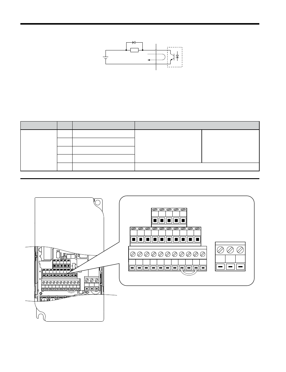
Terminal Configuration
S1
S2
S3
S4
S5
S6
S7 HC SC H1 RP
R+ R–
S+ S–
IG
P1
P2 PC A1
A2
+V AC AM AC MP
MC
MB
MA
S1
S2
S3
S4
S5
S6
S7 HC SC H1 RP
R+ R-
S+ S-
IG
P1
P2 PC A1
A2
+V AC AM AC MP
MC
MB
MA
Figure 3.15 Removable Control Circuit Terminal Block
3.5 Control Circuit Wiring
70
YASKAWA ELECTRIC TOEP C710606 47C YASKAWA AC Drive – V1000 Quick Start Guide