B.1 parameter table – Yaskawa J1000 Compact Vector Control Drive User Manual
Page 198
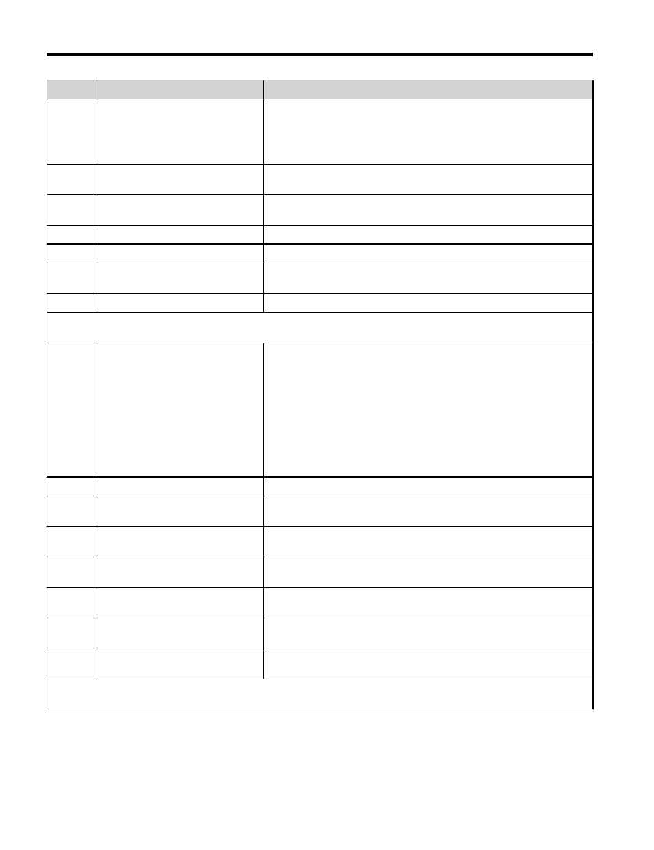
No.
Name
Description
H6-01 Pulse Train Input Terminal RP
Function Selection
0: Frequency reference
1: PID feedback value
2: PID setpoint value
3: Simple PG V/f control mode (can be set only when using motor 1 in
the V/f control mode)
H6-02 Pulse Train Input Scaling
Sets the number of pulses (Hz) that is equal to 100% of the value
selected in H6-01.
H6-03
Pulse Train Input Gain
Sets the level of the value selected in H6-01 when a frequency with the
value set in H6-02 is input.
H6-04 Pulse Train Input Bias
Sets the level of the value selected in H6-01 when 0 Hz is input.
H6-05 Pulse Train Input Filter Time
Sets the pulse train input filter time constant.
H6-06 Pulse Train Monitor Terminal MP
Selection
Select the pulse train monitor output function (value of the - part
of U-).
H6-07 Pulse Train Monitor Scaling
Sets the pulse output frequency in Hz when the monitor value is 100%.
L1: Motor Protection Functions
Use L1 parameters to configure motor protective functions.
L1-01
Motor Overload Protection
Selection
1: General Purpose Motor (Standard Fan Cooled)
2: Drive Dedicated Motor with a Speed Range of 1:10
3: Vector Motor with a Speed Range of 1:100
4: PM Motor with Variable Torque
6: General Purpose Motor (50 Hz)
NOTICE: The thermal protection is reset when the power is cycled.
In applications where the power is frequently cycled, the drive may not
be able to provide protection, even if this parameter is set to 1. Set to
“0” and ensure each motor has a thermal relay installed.
Note: Setting 6 is available in drive software versions PRG: 1016 and
later.
L1-02
Motor Overload Protection Time Sets the motor thermal overload protection (oL1) time.
L1-03
Motor Overheat Alarm Operation
Selection (PTC input)
Refer to V1000 Technical Manual for details.
L1-04
Motor Overheat Fault Operation
Selection (PTC input)
Refer to V1000 Technical Manual for details.
L1-05
Motor Temperature Input Filter
Time (PTC input)
Refer to V1000 Technical Manual for details.
L1-13
Continuous Electrothermal
Operation Selection
Refer to V1000 Technical Manual for details.
L1-22
Leakage Current Filter Time
Constant 1
Refer to V1000 Technical Manual for details.
Note: Available in drive software versions PRG: 1021 and later.
L1-23
Leakage Current Filter Time
Constant 2
Refer to V1000 Technical Manual for details.
Note: Available in drive software versions PRG: 1021 and later.
L2: Momentary Power Loss
Use L2 parameters to configure drive functions for momentary power loss conditions.
B.1 Parameter Table
198
YASKAWA ELECTRIC TOEP C710606 47C YASKAWA AC Drive – V1000 Quick Start Guide