3 switch rear panel, 3 switch rear panel -2 – PLANET WGSW-52040 User Manual
Page 26
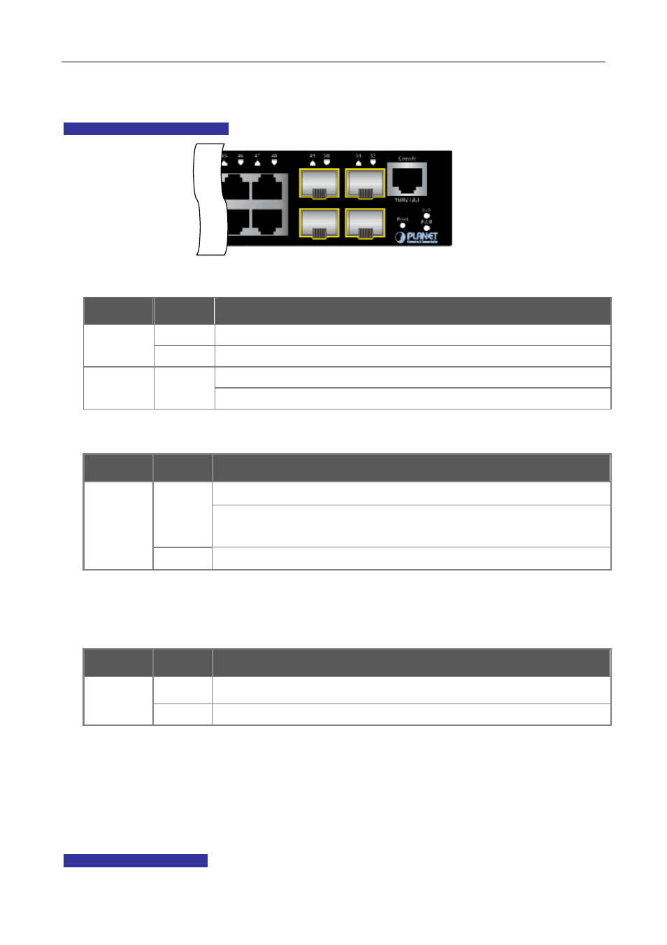
The front panel LEDs indicates instant status of port links, data activity, system operation, Stack status and
system power, helps monitor and troubleshoot when needed.
WGSW-52040 LED Indication
Figure 2-2 WGSW-52040 LED panel
■
System
LED
Color
Function
Green Lights to indicate that the Switch has power.
PWR
Off
Power is off.
Lights to indicate the system diagnoses is completed.
SYS Green
Blinks to indicate boot is enable.
■
10/100/1000Base-T interfaces
LED
Color
Function
Lights to indicate the link through that port is successfully established
Green Blinks to indicate that the switch is actively sending or receiving data over that
port.
LNK/ACT
Off
No flow goes through the port.
■
SFP interfaces
LED
Color
Function
Green Lights to indicate the link through that port is successfully established
LNK/ACT
Off
No flow goes through the port.
2.1.3 Switch Rear Panel
The rear panel of the Managed Switch indicates an AC inlet power socket, which accepts input power from
100 to 240V AC, 50-60Hz.
Figure 2-3
shows the rear panel of this Managed Switch.
WGSW-52040 Rear Panel
2-2