PLANET WGSW-52040 User Manual
Page 321
Multicast router
Multicast Server 1
Multicast Server 2
Multicast port
IGMP Snooping
Group 1
Group 1
Group 1
Group 2
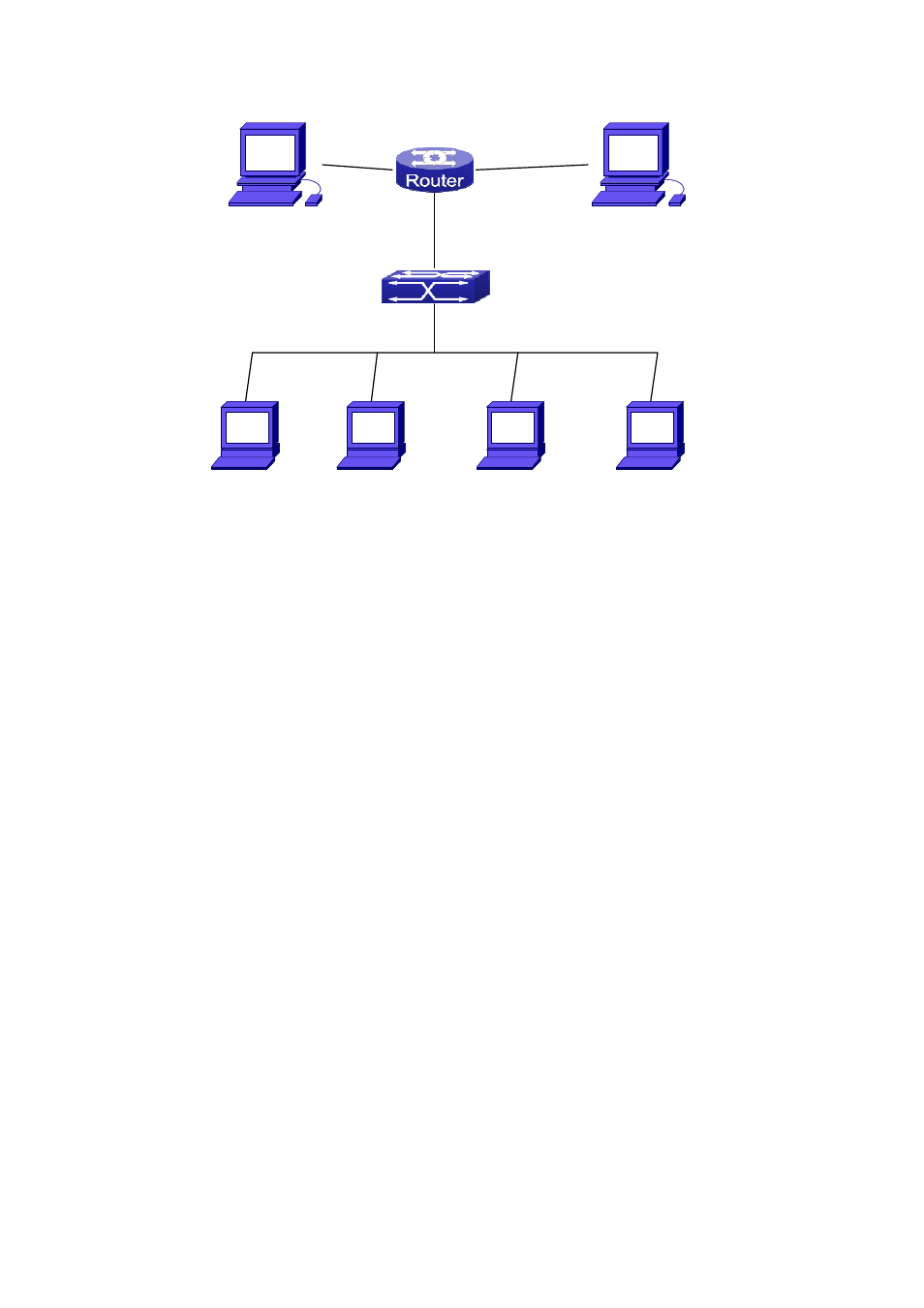
Figure 38-1: Enabling IGMP Snooping function
Example: As shown in the above figure, a VLAN 100 is configured in the switch and includes
ports 1, 2, 6, 10 and 12. Four hosts are connected to port 2, 6, 10 and 12 respectively and the
multicast router is connected to port 1. As IGMP Snooping is disabled by default either in the
switch or in the VLANs, If IGMP Snooping should be enabled in VLAN 100, the IGMP
Snooping should be first enabled for the switch in Global Mode and in VLAN 100 and set port 1
of VLAN 100 to be the mrouter port.
The configuration steps are listed below:
Switch(config)#ip igmp snooping
Switch(config)#ip igmp snooping vlan 100
Switch(config)#ip igmp snooping vlan 100 mrouter interface ethernet 1/1
Multicast Configuration
Suppose two programs are provided in the Multicast Server using multicast address Group1
and Group2, three of four hosts running multicast applications are connected to port 2, 6, 10
plays program1, while the host is connected to port 12 plays program 2.
IGMP Snooping listening result:
The multicast table built by IGMP Snooping in VLAN 100 indicates ports 1, 2, 6, 10 in Group1
and ports 1, 12 in Group2.
All the four hosts can receive the program of their choice: ports 2, 6, 10 will not receive the
38-100