Actuator cycle & travel – Flowserve Logix MD+ ValveSight User Manual
Page 103
ValveSight™ Diagnostics DTM Manual for Logix MD+ Positioner with HART®
FCD-
LGENSF0014-00
© Flowserve Corporation
103
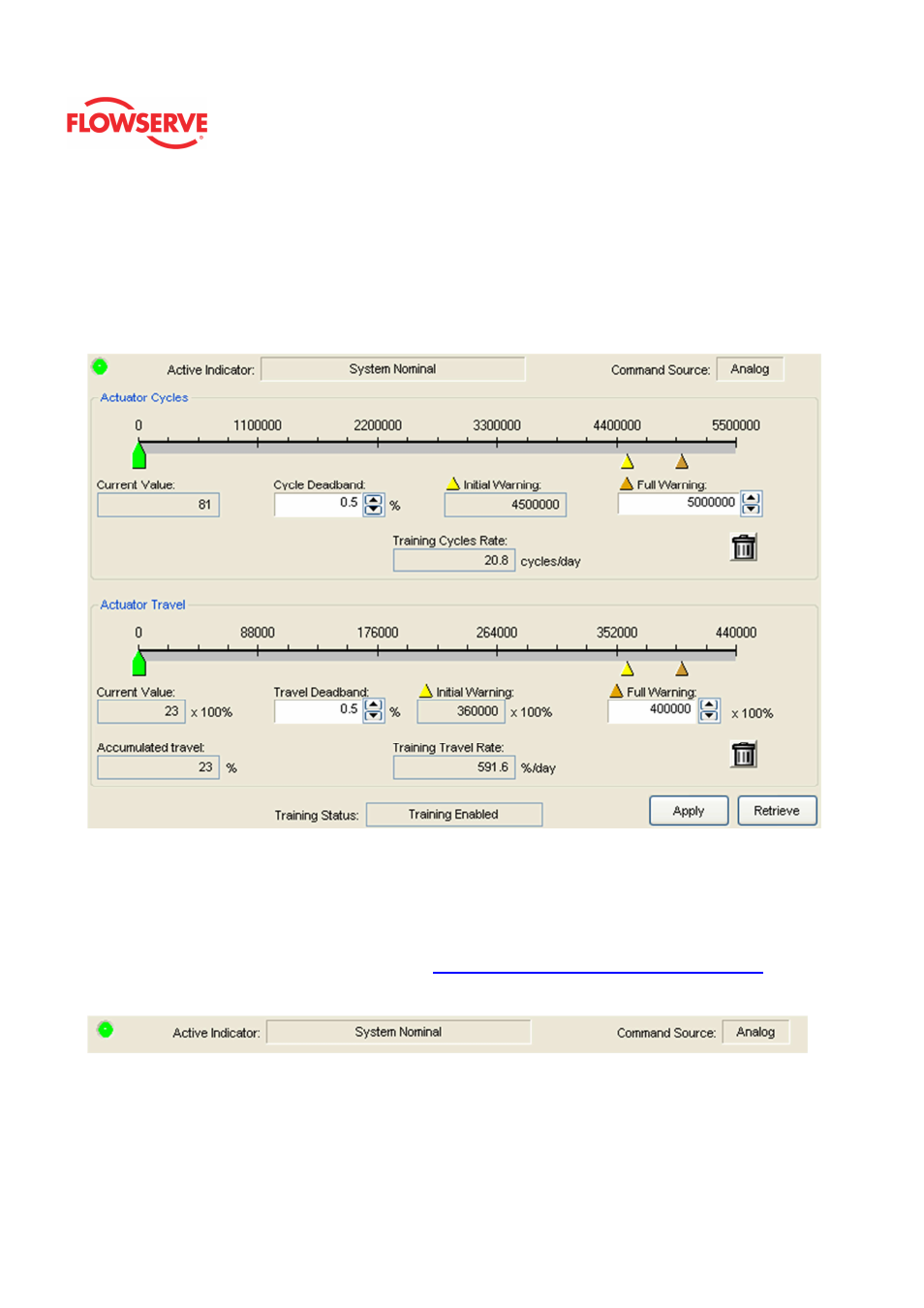
Actuator Cycle & Travel
The Actuator Cycles and Travel page allows you to set warning limits related to the number
of actuator cycles and the actuator travel. The cycles and travel are recorded by the
positioner during normal operation. These limits affect the health bar indicator on the
Dashboard. For example, as the actuator cycles increase and pass the Initial Warning, the
health bar will begin to turn yellow. As it approaches the Final Warning. the health bar will
be completely yellow.
Status Area
The Active Indicator area shows the status of the most relevant active indicator. The color
of the "LED light" corresponds to the Active Indicator and the first color of the blink code
sequence on the positioner. Generally green indicates no immediate issues. Yellow
indicates a developing issue. Red indicates the ability to control may be compromised. A
detailed list of the indicators is given in the
Alarm Congfiguraion - Alarm Annunicator
page.
The Command Source field indicates weather the positioner is being controlled by digital or
an analog (4-20 mA) command source.
Adjusting Limits
There are two ways to adjust the settings.
1. Move the scale indicators. The limits can be adjusted by "dragging" each limit