Flowserve Logix MD+ ValveSight User Manual
Page 74
ValveSight™ Diagnostics DTM Manual for Logix MD+ Positioner with HART®
FCD-
LGENSF0014-00
© Flowserve Corporation
74
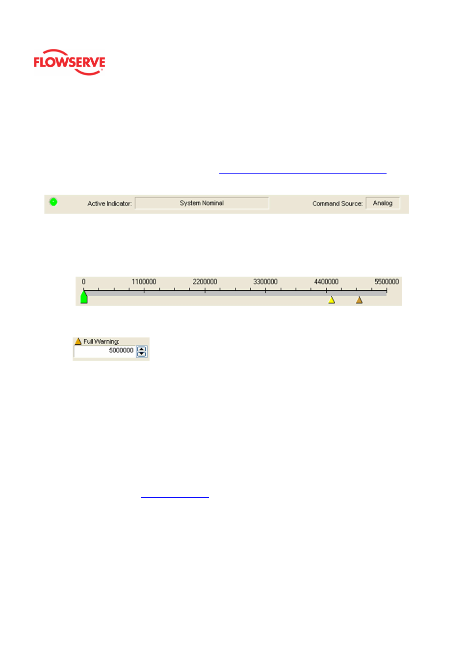
Status Area
The Active Indicator area shows the status of the most relevant active indicator. The color
of the "LED light" corresponds to the Active Indicator and the first color of the blink code
sequence on the positioner. Generally green indicates no immediate issues. Yellow
indicates a developing issue. Red indicates the ability to control may be compromised. A
detailed list of the indicators is given in the
Alarm Congfiguraion - Alarm Annunicator
page.
The Command Source field indicates weather the positioner is being controlled by digital or
an analog (4-20 mA) command source.
Adjusting Limits
There are two ways to adjust the settings.
1. Move the scale indicators. The limits can be adjusted by "dragging" each limit
indicator with a mouse click.
2. Use the input boxes. Numbers can be directly typed. Clicking on the up and
down arrows will also change the value.
NOTE: The apply button must be selected for the changes to take affect.
Set Bellows Cycles Limits
The Current Value is the number of Bellows Cycles counted by the positioner. The Cycle
Deadband is the minimum amount of travel required in each direction before the cycle is
counted. (This is the same variable as Valve Cycles Deadband.) The Initial Warning is the
point at which the Bellows Cycle Warning will begin. The Full Warning is where the health
bar on the Dashboard will show fully yellow. The Full Warning value is the only limit that
can be modified. The Initial Warning is always 90% of the Full Warning value. The reset
button will set the Current Value to zero. The Training Cycle Rate field displays average
number of cycles per day of the bellows during the training period. For more information
about Training, see the
Health - Training
page.