Flowserve Logix MD+ ValveSight User Manual
Page 23
ValveSight™ Diagnostics DTM Manual for Logix MD+ Positioner with HART®
FCD-
LGENSF0014-00
© Flowserve Corporation
23
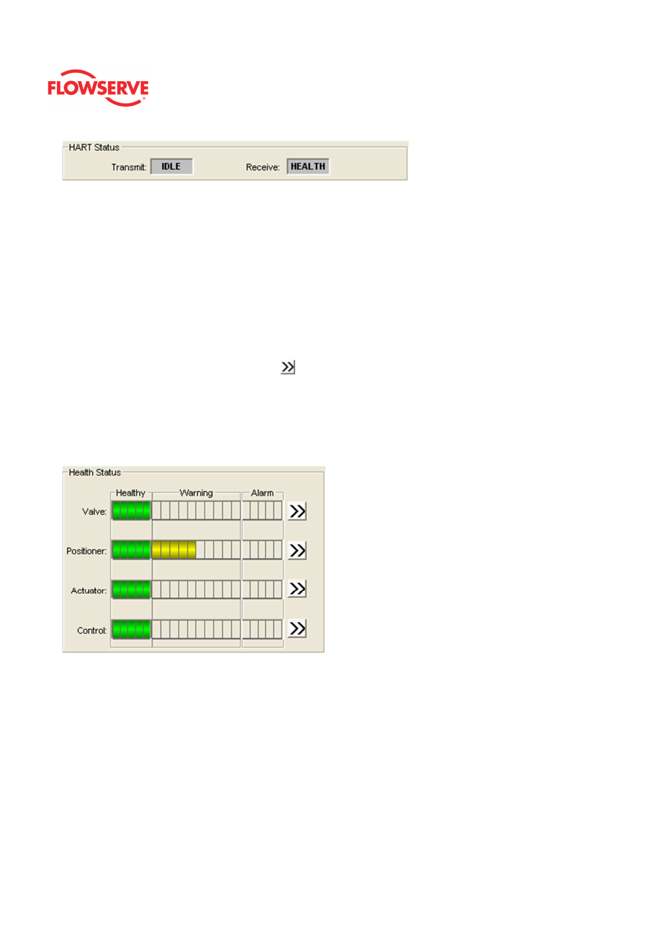
Health Status
The
Health Status box has health indication bars for Valve, Position, Actuator, and Control
which are displayed in 4 bar graphs in the center of the dashboard. These are powerful,
visual diagnostic tools. Information from all of the diagnostic indications are rolled up into
these health bars. As the graphs turn color (from green to yellow to red) they indicate
developing issues. The health of the four key components of a control valve can be
identified quickly by looking at the color of the bar. If the bars only show green then
everything is operating within normal limits and no further action is required. If the bar is
partially yellow it is pointing out a degraded condition. The further the bar goes to the right
the more serious the degradation. If the bar is red then action should be taken immediately
because the ability to control may be compromised. To learn more about any of the 4
health areas, click the double arrows (
) button at the end of the bar. This leads to the
detailed health status page for that particular item.
NOTE: Health Status bars are only available with the Advanced ValveSight® license
viewing positioners with Advanced or Pro diagnostics. See the licensing and upgrade
pages under Positioner Configuration in the DTM for more information.
Dip Switch Configuration
The box shows the current configuration of the DIP switches on the front of the positioner.
These switches should be set on the positioner before calibration. The configuration that is
set by the DIP switches can be overridden in the software using the DTM. (See the
Basic/Local Interface page of the DTM). If this is the case, an X will be shown in the box to
the right of the item. Be careful when changing the configuration in software because
performing a position calibration (Quick-Cal) will reset the configuration according to the
physical DIP switch settings. See you instructions for the positioner for a detailed
explanation of the switches.