Flowserve Logix MD+ ValveSight User Manual
Page 86
ValveSight™ Diagnostics DTM Manual for Logix MD+ Positioner with HART®
FCD-
LGENSF0014-00
© Flowserve Corporation
86
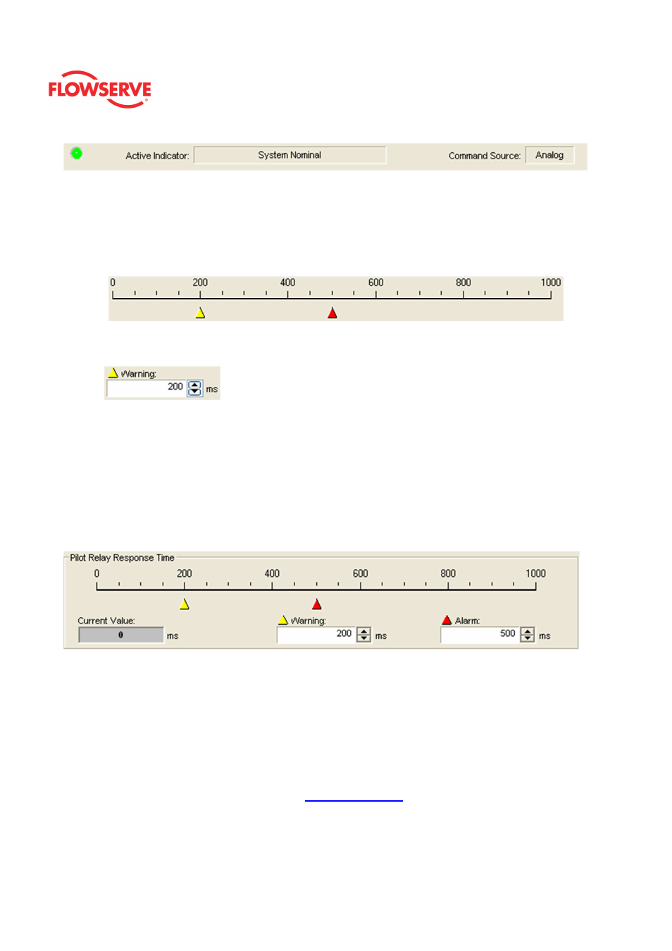
Adjusting Limits
There are two ways to adjust the settings.
1. Move the scale indicators. The limits can be adjusted by "dragging" each limit
indicator with a mouse click.
2. Use the input boxes. Numbers can be directly typed. Clicking on the up and
down arrows will also change the value.
NOTE: The Apply button must be selected for the changes to take affect.
Pilot Relay Response
The
Pilot Relay Response Time is the measure of the time it takes for the pilot relay to
respond. This value is displayed in milliseconds. Normally movement in the relay take less
than 0.05 seconds so a value of 50 or less is normal. The Current Value field displays the
typical time to respond. A response time over the Warning limit will cause the health bar on
the dashboard to turn yellow. A response time over the Alarm limit will cause the health bar
on the dashboard to turn red.
Set Pilot Relay Cycle Limits
The Current Value is the total pilot relay cycles recorded by the positioner. The Initial
Warning is the point at which the Pilot Relay Cycles Warning will begin. The Full Warning
is where the health bar on the Dashboard will show fully yellow. The Full Warning value is
the only limit that can be modified. The Initial Warning is always 90% of the Full Warning
value. The reset button will set the Current Value to zero. The Training Clycles Rate field
displays average amount of cycles per day of the bellows during the training period. For
more information about Training, see the
Health - Training
page.