Flowserve Logix MD+ ValveSight User Manual
Page 277
ValveSight™ Diagnostics DTM Manual for Logix MD+ Positioner with HART®
FCD-
LGENSF0014-00
© Flowserve Corporation
277
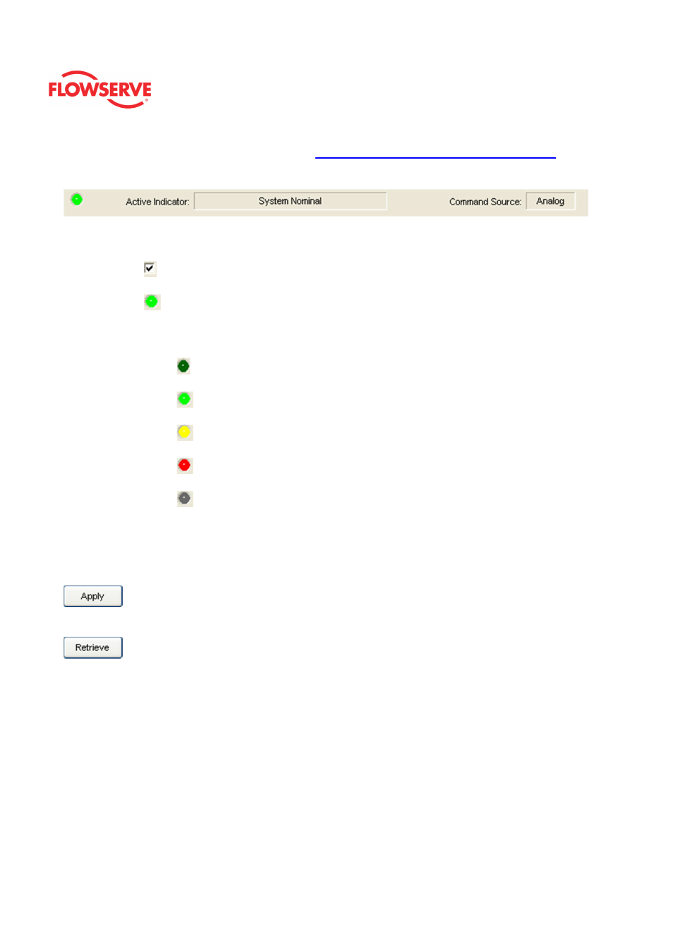
detailed list of the indicators is given in the
Alarm Congfiguraion - Alarm Annunicator
page.
The Command Source field indicates weather the positioner is being controlled by digital or
an analog (4-20 mA) command source.
Legend
Each indicator group box may contain the following components:
•
A checkbox indicates which alarms will cause the DO generate a low
output signal.
•
An "LED light" indicates health status. Warning and alarm limits (set by the
user in many cases) determine the conditions when the color will turn from
green to yellow to red. The most sever of the indicators on this page will be
shown in the health bar on the Dashboard.
•
Dark Green
circle indicates a healthy condition where no attention is
needed.
•
Light Green
indicates an occurrence of a normal activity that does
not affect the health of the valve system.
•
Yellow
circle indicates that an active warning, alert or mode is
present.
•
Red
circle indicates that an active alarm or state is present that
could seriously limit the operation of the valve.
•
Gray
circle indicates that the feature or condition is not available
because the configuration of the hardware or software does not support
it.
Action Buttons
The Apply button will save changes to the connected device.
The Retrieve button will retrieve the latest information from the device.