Command calibration – Flowserve Logix MD+ ValveSight User Manual
Page 203
ValveSight™ Diagnostics DTM Manual for Logix MD+ Positioner with HART®
FCD-
LGENSF0014-00
© Flowserve Corporation
203
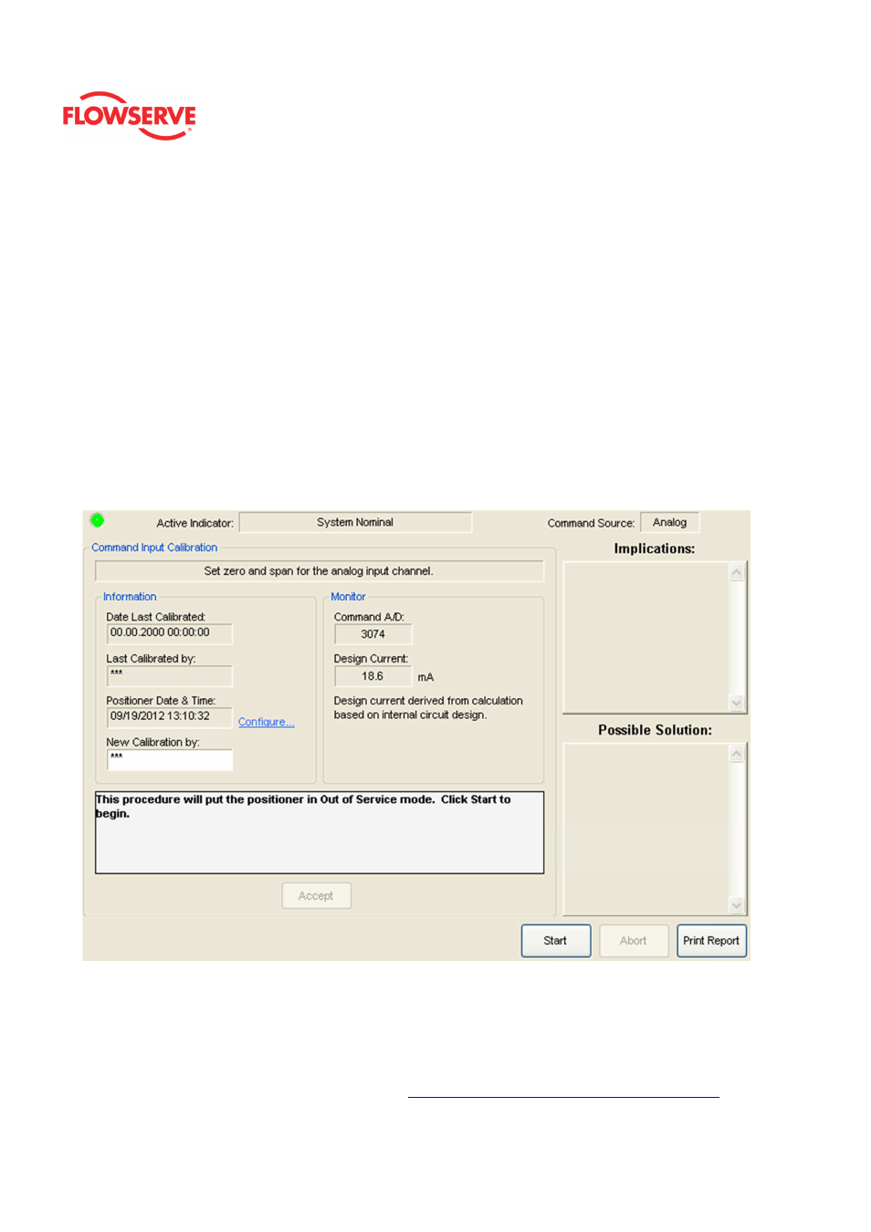
Command Calibration
The
Command Calibration page is used to adjust the range of the positioner input signal.
The default input range is 4 to 20 mA. A split-range calibration can be performed here by
adjusting the input span to something other than 4-20 mA. Once setup properly this
calibration is usually not required for ongoing maintenance.
The command calibration is a step-by-step Wizard calibration. Towards the bottom of the
page, a text field indicates actions required for the next step. When the action indicated in
the text field is completed, click the “Accept” button.
CAUTION: During an input signal calibration, the positioner will not respond to command
changes.
NOTE: An unfiltered external current source must be connected to the positioner in order to
complete the calibration.
Status Area
The Active Indicator area shows the status of the most relevant active indicator. The color
of the "LED light" corresponds to the Active Indicator and the first color of the blink code
sequence on the positioner. Generally green indicates no immediate issues. Yellow
indicates a developing issue. Red indicates the ability to control may be compromised. A
detailed list of the indicators is given in the
Alarm Congfiguraion - Alarm Annunicator
page.