Multi-function card – Flowserve Logix MD+ ValveSight User Manual
Page 270
ValveSight™ Diagnostics DTM Manual for Logix MD+ Positioner with HART®
FCD-
LGENSF0014-00
© Flowserve Corporation
270
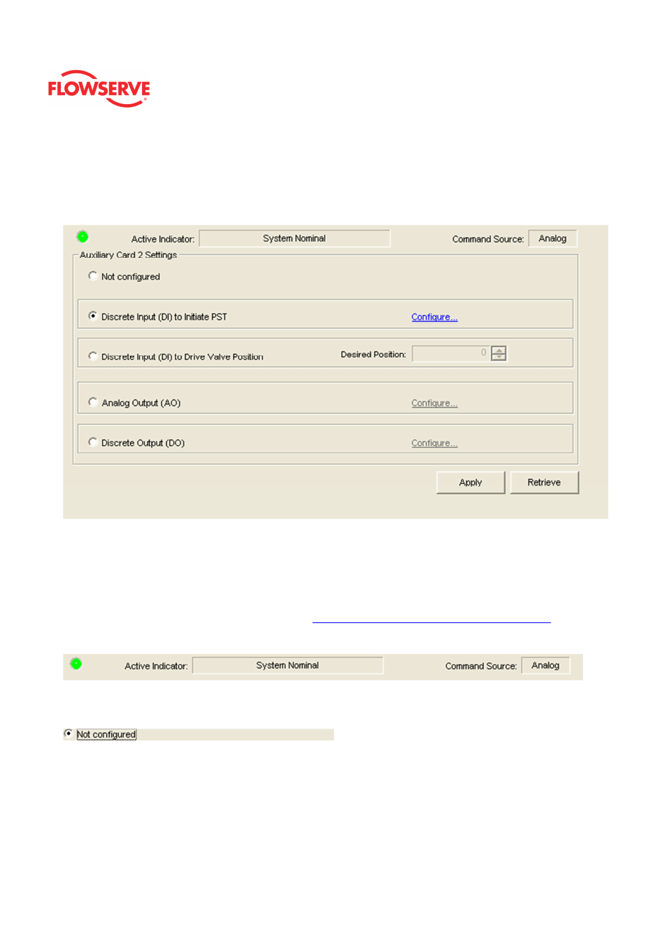
Multi-Function Card
The Multi-Function Card page allows you to configure the Multi-Function Card (MFC) as an
analog output, a discrete output, or a discrete input. This page will only be present if an
MFC is present in a positioner slot. There are two separate versions of the MFC for slot 1
and slot 2.
Status Area
The Active Indicator area shows the status of the most relevant active indicator. The color
of the "LED light" corresponds to the Active Indicator and the first color of the blink code
sequence on the positioner. Generally green indicates no immediate issues. Yellow
indicates a developing issue. Red indicates the ability to control may be compromised. A
detailed list of the indicators is given in the
Alarm Congfiguraion - Alarm Annunicator
page.
The Command Source field indicates weather the positioner is being controlled by digital or
an analog (4-20 mA) command source.
Not Configured
Select Not Configured disable the Card.
Discrete Input (DI) to Initiate PST
Select Discrete Input (DI) to Initiate PST to configure the MFC Card to trigger a partial
stroke test. When over 10 volts are applied to the card, the partial stroke test will be
initiated.
Select Configure link to set the PST settings.