Flowserve Logix MD+ ValveSight User Manual
Page 20
ValveSight™ Diagnostics DTM Manual for Logix MD+ Positioner with HART®
FCD-
LGENSF0014-00
© Flowserve Corporation
20
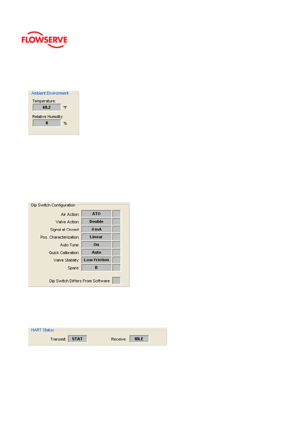
Ambient Temperature
The temperature and relative humidity inside the positioner are shown here. The units for
temperature can be changed in the Positioner Configuration - Units page.
Dip Switch Configuration
The box shows the current configuration of the DIP switches on the front of the positioner.
These switches should be set on the positioner before calibration. The configuration that is
set by the DIP switches can be overridden in the software using the DTM. (See the
Basic/Local Interface page of the DTM). If this is the case, an X will be shown in the box to
the right of the item. Be careful when changing the configuration in software because
performing a position calibration (Quick-Cal) will reset the configuration according to the
physical DIP switch settings. See you instructions for the positioner for a detailed
explanation of the switches.
HART Status
Communication with the DTM is displayed here. The Transmit field displays a data packet
transmitted to the positioner. The Receive field shows data packets received from the
positioner. These are constantly updating. If they appear static, there may be a problem
with communications.