Flowserve Logix MD+ ValveSight User Manual
Page 185
ValveSight™ Diagnostics DTM Manual for Logix MD+ Positioner with HART®
FCD-
LGENSF0014-00
© Flowserve Corporation
185
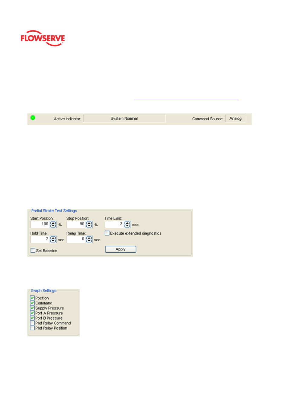
Status Area
The Active Indicator area shows the status of the most relevant active indicator. The color
of the "LED light" corresponds to the Active Indicator and the first color of the blink code
sequence on the positioner. Generally green indicates no immediate issues. Yellow
indicates a developing issue. Red indicates the ability to control may be compromised. A
detailed list of the indicators is given in the
Alarm Congfiguraion - Alarm Annunicator
page.
The Command Source field indicates weather the positioner is being controlled by digital or
an analog (4-20 mA) command source.
Partial Stroke Test Settings
The Start Position and Stop Position are used to specify where the valve position will begin
and end during the step test.
The Time Limit is a limit on how fast the valve must move to within 2% of the final position
in order to pass the test.
The Hold Time is the time the command will remain at the end of the step to allow the valve
to continue moving and stabilize. The test always includes a one-second stabilization
period at the beginning of each test.
The Ramp Time is how long the command will take to reach the stop position.
The Set Baseline check box indicates the signature will be stored in a different memory
location in the positioner. This baseline can remain in the positioner even if other tests are
completed and can be retrieved at any time.
Graph Settings
This area allows for the selection of items to be shown on the graph. All of the data is
acquired (and saved) regardless of this setting. Any item can be hidden or shown after the
data has been downloaded from the positioner.
Monitors
The
Monitors
box shows information regarding the Test Status and the Partial Stroke Test
Progress of the test.