Flowserve Logix MD+ ValveSight User Manual
Page 61
ValveSight™ Diagnostics DTM Manual for Logix MD+ Positioner with HART®
FCD-
LGENSF0014-00
© Flowserve Corporation
61
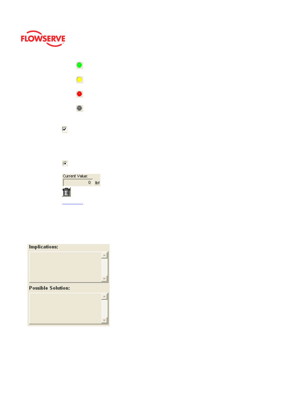
•
Light Green
indicates an occurrence of a normal activity that does
not affect the health of the valve system.
•
Yellow
circle indicates that an active warning, alert or mode is
present.
•
Red
circle indicates that an active alarm or state is present that
could seriously limit the operation of the valve.
•
Gray
circle indicates that the feature or condition is not available
because the configuration of the hardware or software does not support
it.
•
A checkbox indicates the masked status. Check to mask. If a particular
indicator is masked, it will not be shown in the active indicator field at the top
of each screen, affect the status of the health bars on the main dashboard, be
sent in command 48, or be seen on the blinking LEDs on the positioner. It
will however continue to show on this page.
•
A radio button that when selected will show the Implications and Possible
Solutions related to the selected indicator.
•
The current value and units.
•
A button to set values to 0.
•
Configure
A link to redirect the DTM to the configuration page.
Implications and Possible Solutions
When a radio button is checked for an indicator, the related implications and possible
solutions are displayed. The Implications field describes the conditions that trigger the
indicator. The Possible Solutions field describes actions you might take to restore normal
operation.
NOTE: Flowserve does not recommend any action, only lists possible actions that could
restore the system to normal operation. Qualified maintenance personnel should evaluate
the possible solutions, all safety procedures and all other applicable factors on a case by
case basis when determining the best action to take.