Flowserve Logix MD+ ValveSight User Manual
Page 258
ValveSight™ Diagnostics DTM Manual for Logix MD+ Positioner with HART®
FCD-
LGENSF0014-00
© Flowserve Corporation
258
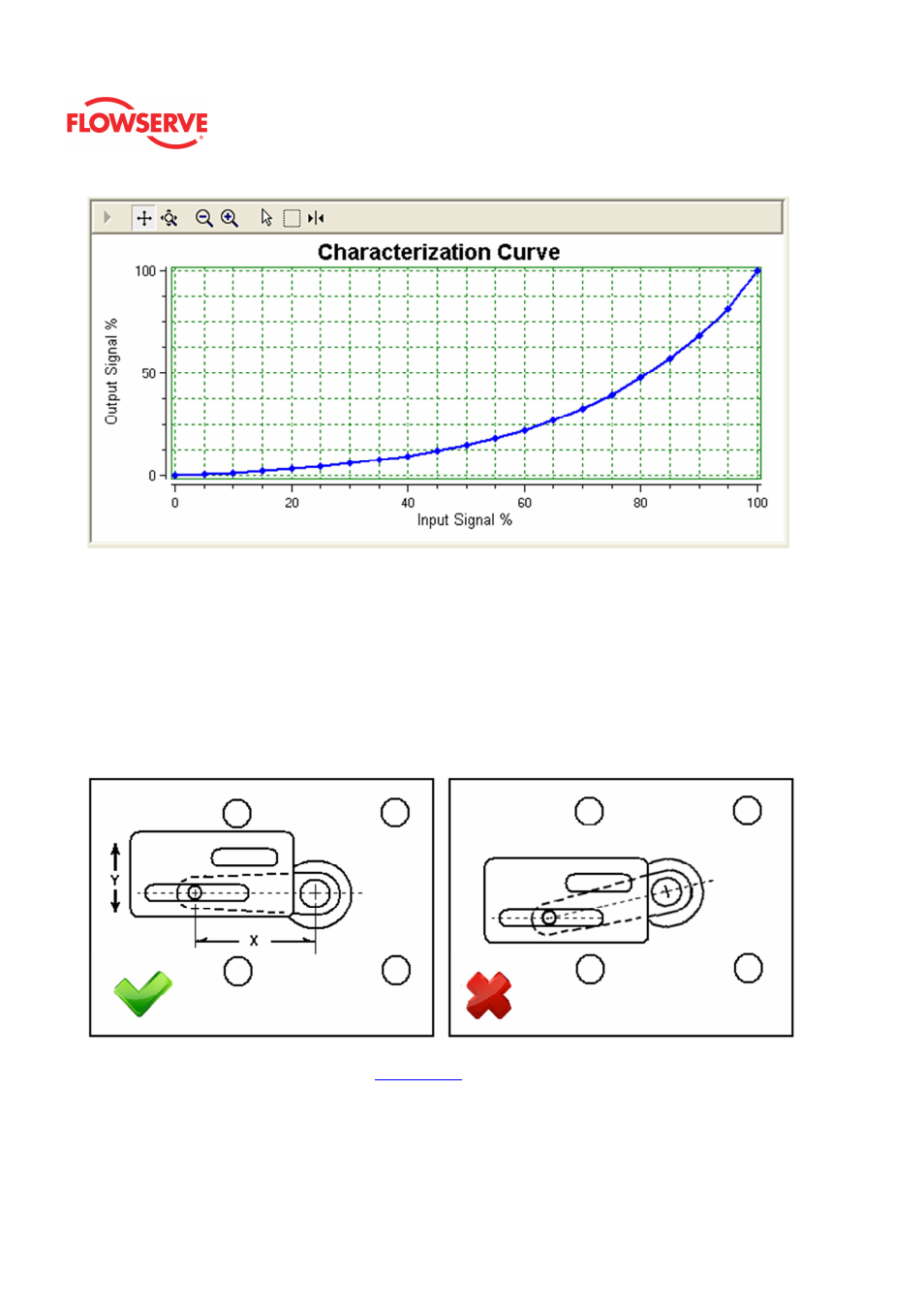
Optional Linkage Linearization Procedure
This procedure is used when position linearity is critical. On linear valves, the configuration
of the positioner's rotating feedback shaft and linkage can introduce a small amount of
nonlinearity when compared to an LVDT (Linear Variable Differential Transformer) or other
external position device. This nonlinearity can be removed using this procedure. As each
step is completed, click the related check box.
1. Ensure a stroke calibration has been performed.
2. Adjust the command signal so the feedback arm is parallel to the slot in the take-off arm
as shown in the diagram.
3. Enter the feedback arm length represented by distance X in the diagram.
4. Verify the stroke length from the
Valve Trim
page. This is the full length of travel in
direction Y in the diagram.
Select the Calculate button.
5. After calculating, the graph will be populated with the new curve. Select the Apply button
to store the curve to the positioner. Then change the characterization settings to Custom.