Valve body – Flowserve Logix MD+ ValveSight User Manual
Page 263
ValveSight™ Diagnostics DTM Manual for Logix MD+ Positioner with HART®
FCD-
LGENSF0014-00
© Flowserve Corporation
263
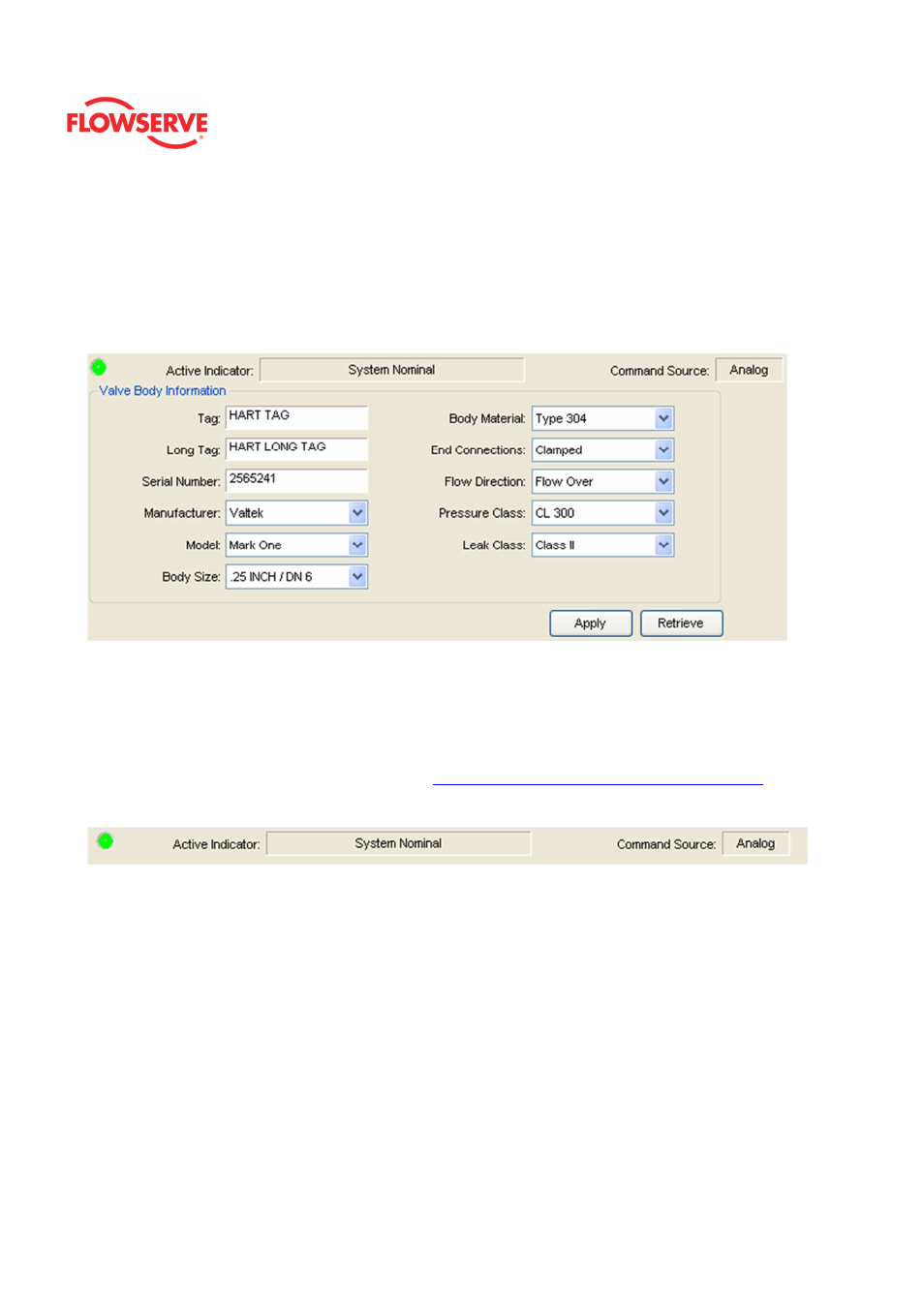
Valve Body
The Valve Body page allows you to record information about the connected valve
assembly.
NOTE: This information is for record keeping and information purposes only and does not
affect the operation of the positioner or control valve.
Status Area
The Active Indicator area shows the status of the most relevant active indicator. The color
of the "LED light" corresponds to the Active Indicator and the first color of the blink code
sequence on the positioner. Generally green indicates no immediate issues. Yellow
indicates a developing issue. Red indicates the ability to control may be compromised. A
detailed list of the indicators is given in the
Alarm Congfiguraion - Alarm Annunicator
page.
The Command Source field indicates weather the positioner is being controlled by digital or
an analog (4-20 mA) command source.
Valve Body Information
Tag stores a name up to 8 characters.
Long Tag stores a name of up to 20 characters (HART 6 and 7 only.)
Serial Number stores a number of up to 10 characters.
The Manufacturer field has a drop down menu of valve manufactures.
The Model field has a drop down menu of valve models.
The Body Size field has a drop down menu of valve sizes.
The Body Material field has a drop down menu of common valve materials.
The End Connections field has a drop down menu of common connection types.
The Flow Direction field has a drop down menu of flow directions (over, under, etc.)
The Pressure Class field has a drop down menu of common pressure classes.
The Leak Class field has a drop down menu of common leak classes.