Flowserve Logix MD+ ValveSight User Manual
Page 210
ValveSight™ Diagnostics DTM Manual for Logix MD+ Positioner with HART®
FCD-
LGENSF0014-00
© Flowserve Corporation
210
ILO Time Out
•
Definition: During calibration the Inner Loop Offset (ILO) value did not
settle. This could result in less accurate positioning.
•
Possible Solutions: Repeat the stroke calibration to get a more
accurate ILO value. To proceed using the less accurate ILO value, this
error may be cleared by briefly pushing the QUICK-CAL/ACCEPT
button. Lowering the setting on the gain selection switch may help if the
actuator is unstable during the calibration.
•
Stroke Shift
•
Definition: The 0% and 100% valve positions have both shifted in the
same direction since the last stroke calibration. This may be related to
a bent or adjusted feedback linkage, loose positioner mounting, or an
over rotated feedback potentiometer.
•
Possible Solutions: Ensure the feedback linkage is not bent and the
positioner is mounted securely. If the feedback potentiometer is over-
rotated, repeat the stroke calibration until the Stroke Shift error is no
longer present. This notification can be cleared by briefly pressing the
QUICK-CAL/ACCEPT button.
Stroke Span Increase
•
Definition: The 0% and 100% valve positions are farther apart
compared to the last stroke calibration. This could indicate seat wear.
•
Possible Solutions: Inspect valve or schedule valve for
inspection. This notification can be cleared by briefly pressing the
QUICK-CAL/ACCEPT button
Stroke Span Decrease
•
Definition: The 0% and 100% valve positions are closer together
compared to the last stroke calibration. This could indicate debris or
build up at valve seat.
•
Possible Solutions: Inspect valve or schedule valve for
inspection. This notification can be cleared by briefly pressing the
QUICK-CAL/ACCEPT button.
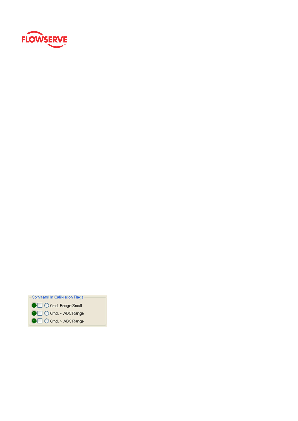
Command Input Calibration Flags
Command Range Small
•
Definition: During a Command Loop Calibration, the difference
between the signal at 0% and the signal at 100% was too small. The
system is designed to accept a difference greater than 5 mA.
•
Possible Solutions: Recalibrate making sure to use a larger
difference between command signal limits. The difference must exceed
5 mA.