Instrument familiarity, Cufflink, Operators manual – Fluke Biomedical Cufflink User Manual
Page 20
Cufflink
Operators Manual
1-8
Instrument Familiarity
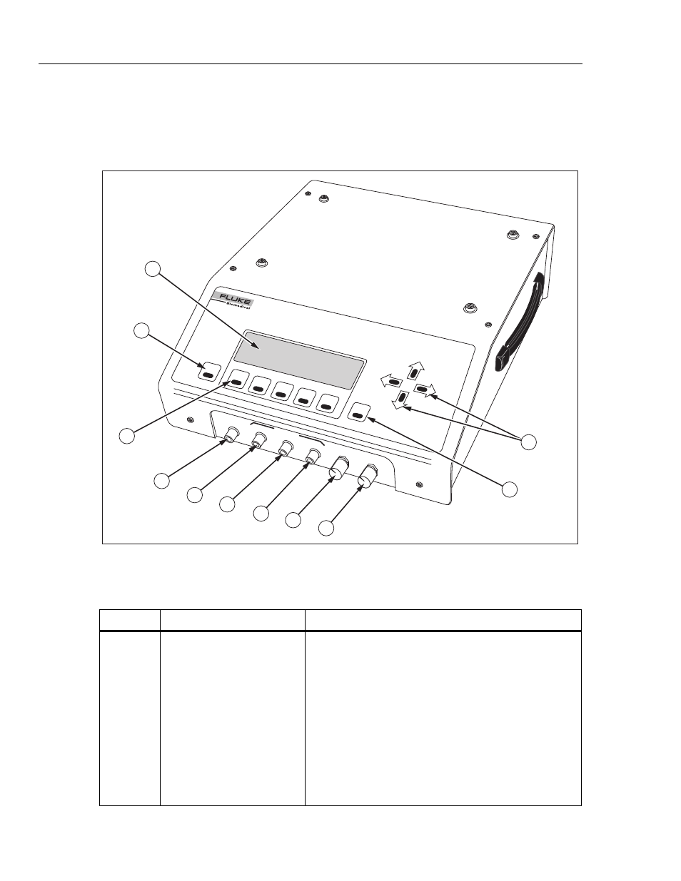
Figure 1-3 shows the top and front panel controls and indicators of the Analyzer.
Table 1-3 lists these components with accompanying descriptions. Figure 1-4 shows the
rear panel controls and indicators, and Table 1-4 lists and describes these components.
F1
ESC
ENT
F2
F3
F4
F5
CuffLink
NON-INV
ASIVE BLOOD PRESSURE A
NALYZE
R
CUFF
CO
NN
ECT
CUFF
OUTPUTS
PULSE
BEEPER
V
OLUM
E
DISPL
AY
V
IE
W
Max
DC
mHg
mmHg
mmHg
Da
rk
1
2
3
4
5
6
7
8
10
11
9
fcv003.eps
Figure 1-3. Analyzer Top and Front Panel Controls and Indicators
Table 1-3. Analyzer Top and Front Panel Controls and Indicators
Label Component
Description
A
Display
The LCD (Liquid Crystal Display) is a full alphanumeric and
graphic display. The maximum number of characters able
to be on a single line at any given time is 40, and the
number of lines from top to bottom is 8, thereby producing a
possible 320 character display. The graphics mode of the
display is defined by a grid of 64 vertical pixels by 240
horizontal pixels. This mode enables display of the cuff
pressure waveform.
Display viewing angle is adjustable, so if the display appears
blank (view angle set too low), or dark (view angle set too
high) the view angle may need to be adjusted for optimum
visibility (see Display View Control Knob).