Making connections – Fluke Biomedical Cufflink User Manual
Page 36
Cufflink
Operators Manual
2-8
Making Connections
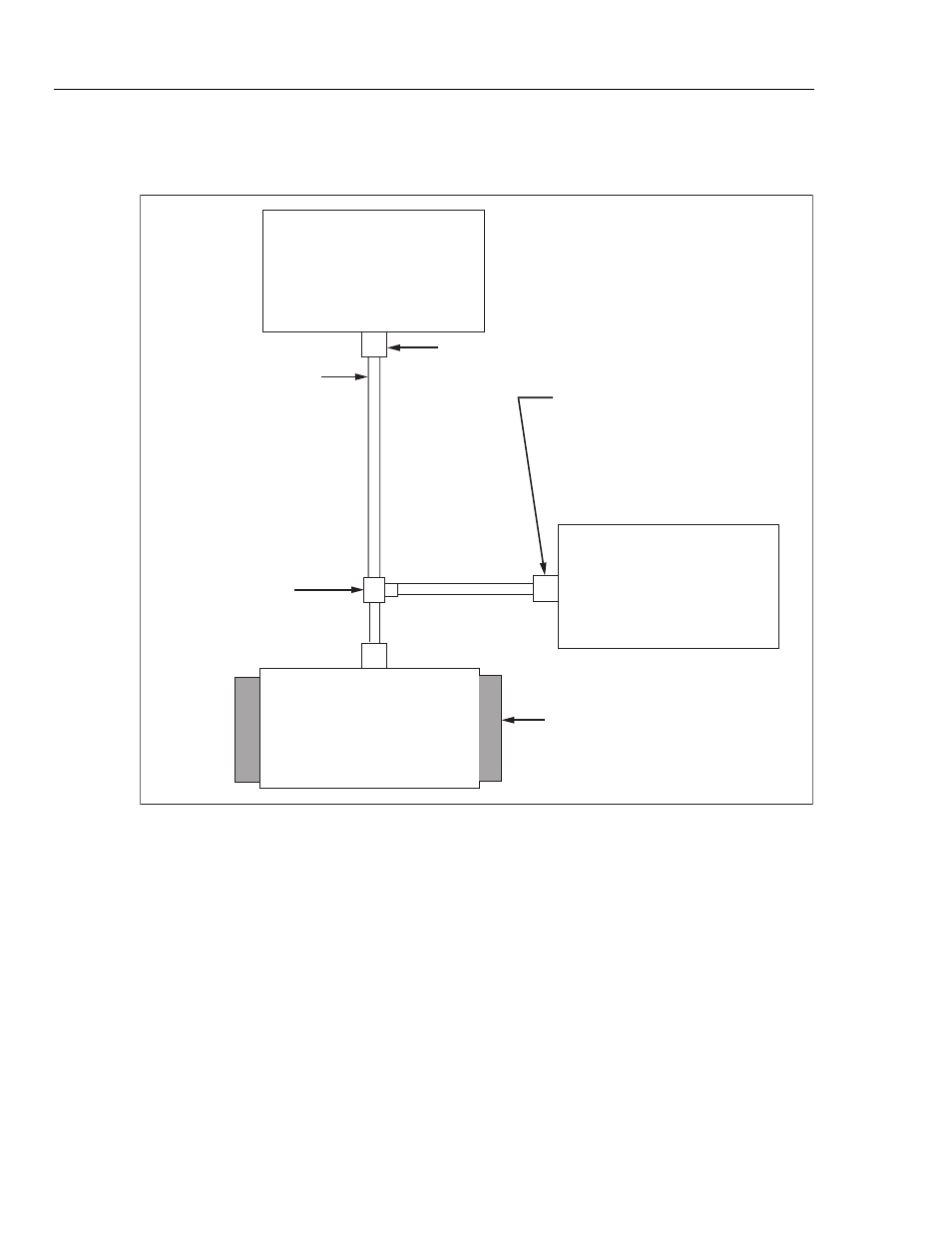
Figure 2-4 is an annotated diagram of the properly-connected test system.
N
IBP Monitor
C
u
ff Connector
“T” Connector
C
u
ff Adapter
C
u
ff Mandrel
C
u
ff Connect Port
(front panel)
To connect: P
u
sh C
u
ff Adapter
in
u
ntil a click is heard.
To disconnect: p
u
sh slee
v
e
b
ack to release C
u
ff Adapter.
M
u
st
b
e connected closer
to c
u
ff than monitor
C
u
fflink
BP C
u
ff
W
raps aro
u
nd mandrel
Pne
u
matic Hose(s)
D
u
al hose systems: connect
C
u
ff Adapter to hose
marked “Sense”. If
b
oth
hoses are
u
nmarked,
connect C
u
ff Adapter to
either hose.
fcv015.eps
Figure 2-4. NIBP Test System Diagram
To correctly connect the components of the test system:
1. Attach the BP cuff to the NIBP monitor as shown in Figure 2-4. Refer to the monitor
operators manual, as necessary.
2. Wrap the cuff tightly around the appropriate mandrel. See Figures 2-2, and 2-3.
3. Connect the cuff adapter T connector into the line nearest the cuff.
If the NIBP monitor has two pneumatic hoses connected to the cuff, insert the cuff
adapter into the hose labeled Sense. If neither hose is labeled, insert the cuff adapter
into either hose.
Note
Do not connect the cuff adapter to the Analyzer until the Analyzer has
warmed up for at least 15 minutes.
4. Power up both the Analyzer and the NIBP monitor.