Introduction and specifications, Instrument familiarity – Fluke Biomedical Cufflink User Manual
Page 23
Introduction and Specifications
Instrument Familiarity
1
1-11
I
115
O
FUSE T3.15a 100-115
V
AC 50/60Hz
FUSE T1A 200-230
V
AC 50/60Hz
I
N
PUT PO
W
ER 60
V
A
C
u
ffLink sn 34
8
0
FLUKE BIOMEDICAL CORPORATIO
N
CARSO
N
CITY,
N
E
V
ADA
MADE I
N
THE U.S.A
PRI
N
TER
SERIAL
N
UMBER
34
8
0
RS232
2
3
4
5
1
6
7
9
8
fcv004.eps
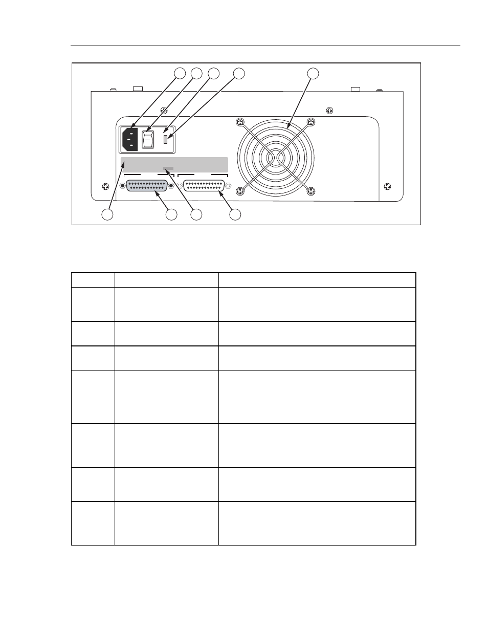
Figure 1-4. Rear Panel Controls and Indicators
Table 1-4. Rear Panel Controls and Indicators
Label Component
Description
A
Power Cord Input
The input for the Cufflink power cord is located next to the
power switch. This is the connection for the detachable
power cord.
B
Power Switch
The on position of the power switch is represented by 1 and
the off position is labeled 0.
C
Fuse Cover
The fuse(s) are located behind the fuse cover. The fuse
cover may be carefully pried open at 3a.
D
Voltage Selector
CuffLink is able to operate on two different line voltages.
The voltage selector indicates the voltage (either 120V or
240V) at which CuffLink will operate. There are an
additional two voltages (100V and 220V) listed on the back
panel. These do not apply to CuffLink.
E
Fan Intake
A hole cut in the rear panel of the case provides ventilation
for Cufflink from the fan. Care should be exercised not to
block the fan intake or to insert anything into the metal
protector.
F
RS232 Port
This is the connector for the RS-232 serial interface. It
is a 25 pin (DB25), male, D shell connector (same
pinout as PC compatible computer).
G
Printer Port
The connector for the parallel printer is a 25 pin
(DB25), female, D shell connector. The printer port is
Centronics compatible (same pinout as a PC
compatible computer).