2 regenerative unit options and peripheral devices, Regenerative unit options and peripheral devices – Yaskawa R1000 Series Power Regenerative Unit User Manual
Page 138
138
YASKAWA ELECTRIC TOEP C710656 08B YASKAWA Power Regenerative Unit - R1000 Instruction Manual
7.2 Regenerative Unit Options and Peripheral Devices
7.2 Regenerative Unit Options and Peripheral Devices
lists the names of the various peripheral devices, accessories, and options available for Yaskawa regenerative
units. Contact Yaskawa or your Yaskawa agent to order these peripheral devices.
• Peripheral Device Selection: Refer to the Yaskawa catalog for selection and part numbers.
• Peripheral Device Installation: Refer to the corresponding option manual for installation instructions.
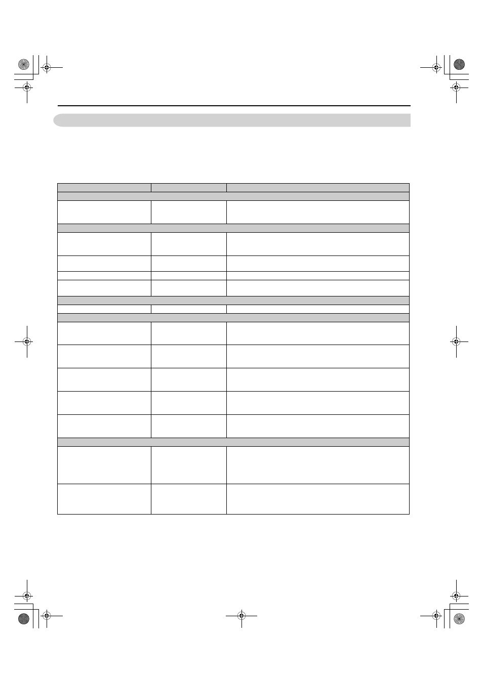
Table 7.1 Available Peripheral Devices
Option
Model Number
Description
Power Options
24 V Power Supply
PS-A10LB (200 V class)
PS-A10HB (400 V class)
Provides power supply for the control circuit and option boards.
Note: Parameter settings cannot be changed when the drive is operating
solely from this power supply.
Interface Options
USB Copy Unit (RJ-45/
USB compatible plug)
JVOP-181
• Can copy parameter settings easily and quickly to be later transferred to
another regenerative unit.
• Adapter for connecting regenerative unit to the USB port of a PC.
PC Cable
Commercially available
USB2.0 A/B cable.
Connect regenerative unit and PC when using DriveWizard Industrial.
The cable length must be 3 m or less.
LED Operator
JVOP-182
5-digit LED operator; maximum cable length for remote usage: 3 m
LCD Operator Extension Cable
WV001: 1 m
WV003: 3 m
Cable for connecting the LCD operator.
Mechanical Options
Attachment for External Heatsink
–
Attachment for External Heatsink
Communications Option Cards
MECHATROLINK-II Interface
SI-T3
Used for running or stopping the regenerative unit, setting or referencing
parameters, and monitoring input current, output voltage, or similar items
through MECHATROLINK-II communication with the host controller.
CC-Link Interface
SI-C3
Available soon.
Used for running or stopping the regenerative unit, setting or referencing
parameters, and monitoring input current, output voltage, or similar items
through CC-Link communication with the host controller.
DeviceNet Interface
SI-N3
Available soon.
Used for running or stopping the regenerative unit, setting or referencing
parameters, and monitoring input current, output voltage, or similar items
through DeviceNet communication with the host controller.
PROFIBUS-DP Interface
SI-P3
Available soon.
Used for running or stopping the regenerative unit, setting or referencing
parameters, and monitoring input current, output voltage, or similar items
through PROFIBUS-DP communication with the host controller.
CANopen Interface
SI-S3
Available soon.
Used for running or stopping the regenerative unit, setting or referencing
parameters, and monitoring input current, output voltage, or similar items
through CANopen communication with the host controller.
Monitor Option Cards
Analog Monitor
AO-A3
Outputs analog signal for monitoring the output state (input frequency,
output voltage etc.) of the regenerative unit.
Output resolution: 11 bit signed (1/2048)
Output voltage: 0 to 10 Vdc (non-isolated)
Terminals: 2 analog outputs
Digital Output
DO-A3
Outputs isolated type digital signal for monitoring the run state of the
regenerative unit (alarm signal, during run, etc.)
Terminals: 6 photocoupler outputs (48 V, 50 mA or less)
2 relay contact outputs (250 Vac, 1 A or less 30 Vdc, 1 A or less)
TOEP_C710656_08B_1_0.book 138 ページ 2015年2月5日 木曜日 午前10時7分